10
11
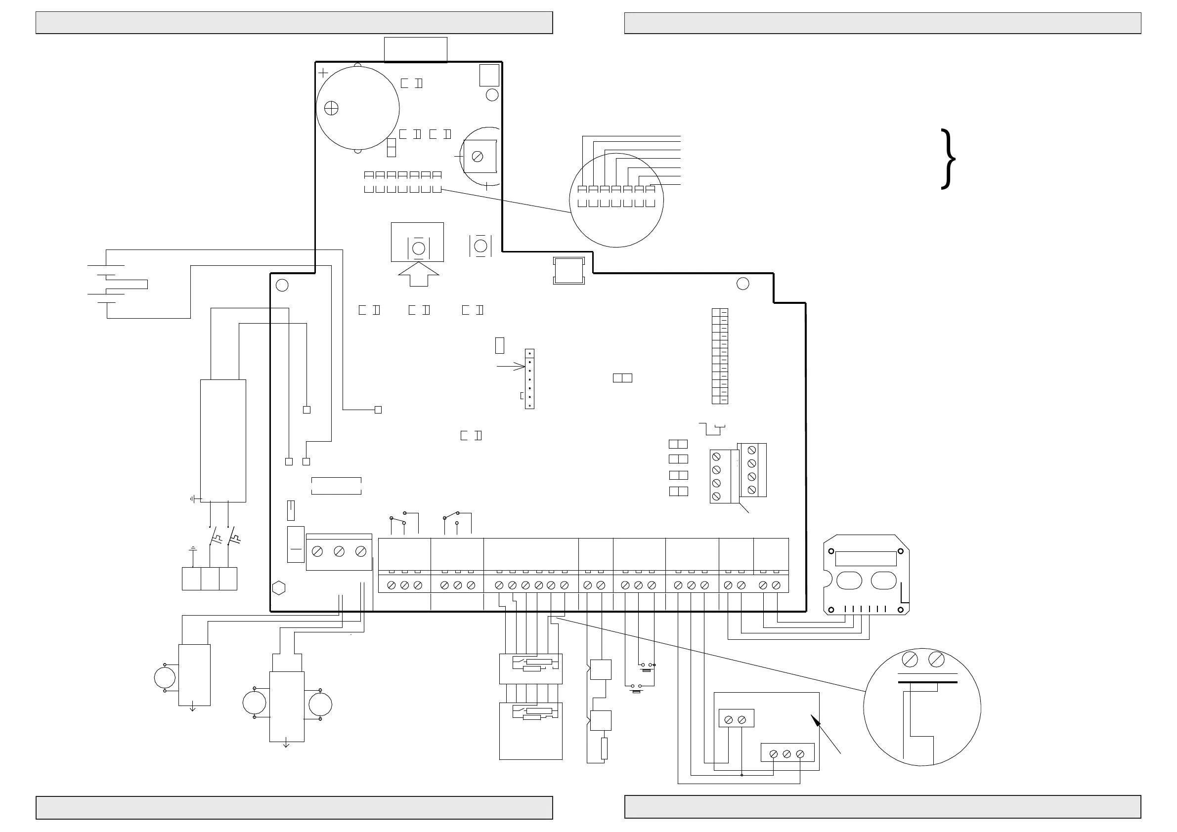
Control for Fire and Comfort Ventilation Type SVM EI 24V-5A / SVM EI 24V-8A
Control for Fire and Comfort Ventilation Type SVM EI 24V-5A / SVM EI 24V-8A
PriorWeather
J11
K11
#111961
AWR-24
24V
®
2,2KΩ
Blue
1 Cannel LIP 7
M2
12
5
6
LIP #2
M1
8
7
34
Brown
2 channel LIP 6
Next LIP
Brown
Blue
Next LIP
Max. Torque 0.5 Nm
Max. Torque 0.5 Nm
Open
24
Close
25 27
Gnd
NO FOIL
26
Keyboard
T
OpenLed
RESET
NO
NC
COM
AC/DC
B4
A4
RED
GRE
#111960
RED
RED
RED
RED
RED
®
Manuel Control Point Smoke Comfort
R
E
S
E
#111980
See page 12
}
RED
ALARM
GRE
OK
YEL
FAILURE
J8
BUZZER ON/OFF
RED
RED
RED
RED
RED
GRE
RED
LED 1 Actuator open (red). Lit when actuator is opening.
LED 2 Actuator closing (green). Lit when actuator is closing.
LED 3 Weather sensor active (red). Lit when weather sensor is active.
LED 4 Line failure actuator (red). Lit for line failure on actuator.
LED 5 Line failure fire switch (red). Lit for line failure on fire switch.
LED 6 Line failure smokesensor (red). Lit for line fail. on smokes.
LED 7 BUS failure (red). Lit when local unit is not recieving signal.
LOCKOUT
TEMP DETECT
SERVICE TIMER
SNITCH
FAIL RELAY M.
WEEK OPEN
OPTION
SPRINKLER
BUS COMFORT
BUS FIRE
12
3
4
6
7
5
8
11
9
10
BUS Master
BUS Slave
END termination
Puls
Max.
Potmeter for
comfort features
Con. Fire. Sig
FAIL SAFE
Min
Co
n
s
t
.
BATT LOW
P
u
l
s
v
a
r
i
a
b
l
e
YEL
LINE FAILAC FAIL
YEL YEL
BAT +
BAT -
ON
®
DIP NO.
1
2
OFF
®
START termination
DOME OPEN
BLUE
PS +
PS -
-
+
+
Black 2,5mm2
-
- 24VDC +
Batteries 2x 12V - 7,2 Ah
24V Red 2,5mm2
Connection
SVM EI 24V - 5A/8A
BUZZER
B3
®
J5
J6
J7
A3
B1 B2
®
®
Serial Out
next unit.
Connection to
®
A1
prev. unit.
®
2120
Gnd
2322
Weather
Gnd
24V
A2
Serial In
Connection from
Bus connection for serial connection
up to 35 pcs. control units.
®
J4
Set J11 for batteri backup
of terminal 23
18
Up
17
Smoke
16
Gnd
19
Down
13
24V
ALARM
Fail. 24V
1211
FIRE
Gnd
15
Reset
14
COM
7
NO
NC
98
Failure OutAlarm Out
NC
5
COM
4
NO
6
3
OK 24V
10
L1 Out
L1 In
No.1
L2
L1 In
L2
Up
2,2KΩ
Fire switch BVT No. 1
10 KΩ
1 32 6 74
J1
Red LED
Yellow LED
Green LED
Extra relay print #111933
provides 2 additional
potential free contacts
each 30V 0,5A
Potential free ALARM switch.
Com + NO connected on alarm.
Max 48V 0,5A
Potential free Failure switch.
Com + NO connected on failure.
Max 48V 0,5A
heat sensors
Smoke or
Down
10 KΩ
L1 Out
Comfort
1
2
3
4
7
6
10 KΩ
J1
Fire switch type BVT.
Fit J1 in last BVT for
line monitoring
(only last sensor)
Connection diagram SVM EI 24
Drawing: 211863_B
1 23 4
7
6
Nr.2-20
Switch
Wind and rain sensor
Max. 8A
FUSE F1 - fast
J 34
J2
12
Line 1
1
2
N1
3
13 A Autofuse
PE L1
1
Blue
2
M1
Brown
1
2
6
LIP #1
5
Actuator
Actuator
Motor line monitor
Ext 3 wire monitor (line 1)
24V Out
PS1
Power Supply 180-250 VAC
24VDC 150W/200W
NTC
J9
Without keyboard jumper mounted
J1
DIP settings see page 13
REMOTE
no: 111894
GND
LED
OPEN
CLOSE
61
Firemans Priority switch
OPENCLOSE


 To Next Page