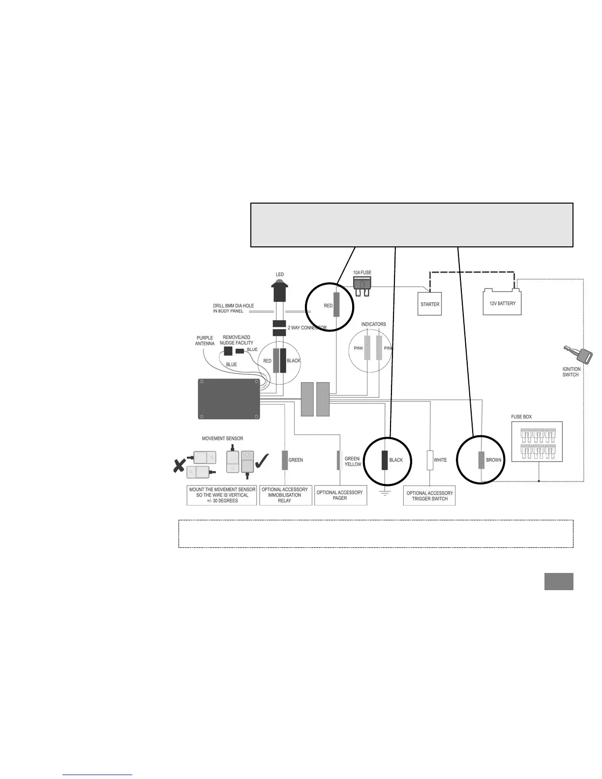
Installation and Wiring
Connect the system wires as
follows:
A larger version of the wiring diagram
can be found on the back page.
The
RREEDD
wire is the alarm positive feed.
DO NOT connect this directly to the
motorcycle battery, but connect to the
positive terminal of the starter solenoid.
Use the Red-tagged ring terminal from
the fit kit.
The
BBLLAACCKK
wire is the alarm negative
connection. Connect this wire to a
suitable earthing point on the motorcycle
frame. DO NOT connect to the battery
negative terminal. Do NOT connect it to a
sub-frame or fairing-frame. An ideal spot
is the connection of the motorcycle
battery negative lead & frame. Use the
Blue-tagged ring terminal from the fit kit.
The
BBRROOWWNN
wire should be connected
to a circuit which becomes live when the
ignition is switched on. Ideally, this
should be connected between the
ignition switch and the motorcycle fuse
box. If this is not practical, a good place
is the feed to the rear brake light switch.
Acumen recommends this connection is
soldered.
CCoonnnneecctt tthhee 66--wwaayy ccoonnnneeccttoorrss ttooggeetthheerr
aanndd pprroocceeeedd ttoo OOppeerraattiioonn
To make the alarm active, you only need to connect the
RReedd,, BBllaacckk
and
BBrroowwnn
wires
TToo ggeett ffuullll bbaassiicc ooppeerraattiioonn ooff tthhee CCAATT33..11 SSyysstteemm,, AAccuummeenn rreeccoommmmeennddss
tthhaatt yyoouu aallssoo ccoonnnneecctt tthhee PPIINNKK ((iinnddiiccaattoorrss)) aanndd BBllaacckk//RReedd ((LLEEDD)) wwiirreess ((sseeee ppaaggee 33))
Should you require further options on the CAT3.1 system, please see Optional Wiring (page 3)
2
 Loading...