EN • 7
ENGLISHFRANCAISNEDERLANDSESpAñoLITALIANoDEuTSCH
662Y0500 • B
COMMISSIONING
COMMISSIONING AND ADJUSTMENT
Adjustment by a qualified technician is essential to obtain a
permanently high combustion quality and operational safety.
When the oil pre-heater is switched on, the burner starts up once
the required temperature has been reached.
Ignition and oil release occur automatically via the automatic oil
firing device.
With some pumps, the oil pressure is displayed only
when the solenoid valve has opened.
If no oil is delivered when it is suctioned for the first time, discontinue
after 3 minutes at the most to avoid damaging the pump. Operating
status is reached when the oil filter is filled with oil.
With oil-air ratio regulators, the oil pressure must be readjusted
to the inherent boiler and chimney ratios (see diag.).
The chimney draught should not exceed – 0.1 mbar.
When the boiler is at operating temperature, check the
combustion values, starting with the CO2value. This value
determines the degree to which the oil flow rate must be modified
for a predetermined air volume:
CO2 < 13.5%: the oil pressure can be increased
CO2 > 13.5%: the oil pressure must be reduced.
Check the CO value when the CO2value has been adjusted to
13-14%. A CO reading of over 40 mg/kWh indicates that the
CO2 value has been distorted by an air leak in the boiler or flue
pipe connection. Seal up any leakages in the boiler and repeat
the measurement. Poor combustion can also be caused by an
unsatisfactory nozzle spray action. The oil pressure may also be
too high.
Note: The CO values in boiler systems can be affected by
combustion residues.
To correctly measure the CO2value the boiler must be
sealed and there must be a flue gas connection, since
any air leaks will falsify the reading!
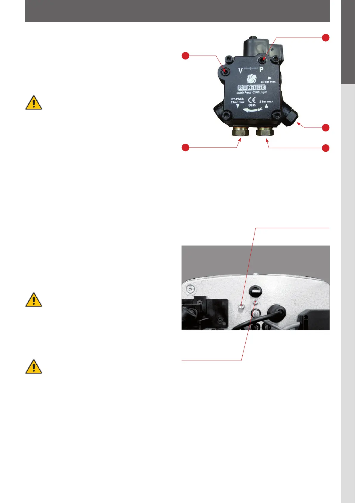
PUMP PRESSURE ADJUSTMENT
Use the pressure regulator to adjust the pump pressure.
To the right: pressure increases; to the left: pressure decreases.
Do not turn the pressure regulator before venting the
pump!
CHANGING THE BURNER CAPACITY
The burner is preset as shown in the diagram and can be
adjusted by ± 8 %.
FAN COMPRESSION
For adjustment control, the fan compression must be measured
by loosening the screw.
1
3
2
5
4
1. Vacuum gauge connection
2. Pressure regulator
3. Manometer connection
4. Pump return
5. Pump flow
Do not turn the
adjustable screw on
the nozzle assembly!
Measurement port for determining
the fan compression.
Switch off power supply when
working on the burner!