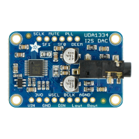
Three pins are used for stereo I2S data in. These pins
are required!
These can be 3.3-5V logic
WSEL (Word Select or Left/Right Clock) - this is the
pin that tells the DAC when the data is for the left
channel and when its for the right channel
DIN (Data In) - This is the pin that has the actual
data coming in, both left and right data are sent on
this pin, the WSEL pin indicates when left or right
is being transmitted
BCLK (Bit Clock) - This is the pin that tells the
amplifier when to read data on the data pin.
MCLK is not required to use this DAC, if you have an
MCLK pin on your audio source, leave it disconnected.
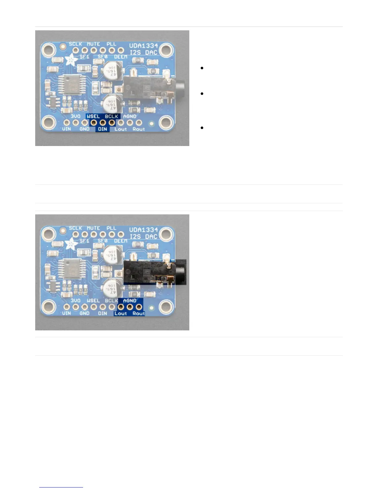
Audio Outputs
The exciting part! This is where your line level audio
comes out. We put big 47uF blocking capacitors on the
output so you can connect this to any stereo system.
AGND is a clean analog ground signal that we
recommend using as your analog reference, you'll get a
cleaner signal.
Note that this DAC was intended for use with a separate
amplifier and is rated for a 3 KΩ load. However, we've
found you
can
plug in 32Ω headphones and the output
is current-limited so it won't damage the DAC but you
will get distortions. (Powered headphones won't have
this issue)
Optional Control Pins
There are some extra configuration pins if you want to use them. They are not required for 99% of usage with an
Arduino or Teensy or Raspberry Pi. But you never know! So they are there for you. PLL and SF0 are 3.3V logic only,
the other pins are 3-5V safe.
Most of the pins have to do with changing the setup from audio mode to video mode. If you happen to want video-
mode, for synchronizing with NTSC/PAL, check the datasheet - we haven't used it for that purpose.