Do you have a question about the AddEnergie CoRe+V2 and is the answer not in the manual?
Device compliance with Industry Canada licence-exempt RSS standard(s), outlining operational conditions.
FCC compliance for Class A digital device, radio frequency energy, and operational conditions for USA.
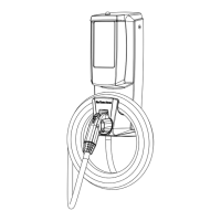
Details on CoRe+V2, CoRe+VBV2, and CoRe+PSV2 models, their features and capabilities.
Specifies the J-1772 compliant output connector and maximum output current/power for various models.
Lists relevant CSA and UL standards for personnel protection systems and EV supply circuits.
Key warnings and precautions for installation, including fire/shock risks and manual screwdriver use.
Essential installation rules: circuit protection, grounding, contractor communication, and no part alteration.
Safety notes on supervision, connector handling, cable/enclosure condition, and charging requirements.
Instructions for routing power cables under the station for wall or post mounting.
Steps for attaching the head base using anchors and connecting L1, L2, and GND conductors.
Procedure for routing power cables from the back of the station.
Instructions for connecting L1, L2, and GND conductors to the terminal block.
Steps for mounting the station head base with an electrical box in the wall or post.
Details on connecting L1, L2, and GND conductors when using an electrical box.
Instructions for connecting data and ground cables to their respective connectors.
Steps for installing the head to the base, ensuring seals are in place and installing mounting screws.
Expected status light and display messages immediately after applying power.
Procedure for scanning an access card and expected results, including beep and authentication.
Details on the automated test of protection circuit, status light, and vehicle charging initiation.
Explains the PowerSharing capability allowing up to four stations on one branch circuit.
Details on enabling dynamic current sharing with a site controller and maximum circuit capacity.
Illustrates a typical installation of multiple CoRe+PS stations sharing a 40A circuit.
| Brand | AddEnergie |
|---|---|
| Model | CoRe+V2 |
| Category | Battery Charger |
| Language | English |