MOUNTING INSTRUCTIONS
Each 4192SDM detector is supplied with a mounting bracket kit that permits the detector to be mounted using several
techniques.
1. Units maybe mounted directly to a 3-inch or 4-inch, 1-1/2-inch deep octagonal electrical box using the supphed mount-
ingbracket (See Figuresl and 2).
2. Units maybe mounted to a 4-inch square electrical box by using a plaster ring with the supplied mounting bracket.
3. Units maybe mounted directly to the ceiling using the plastic screw anchors packed with the bracket. For direct mount-
ing, the bracket is used asatemplate and 3/16-inch holes aredri[led forthe screw anchors.
TAMPER RESISTANCE
This detector includes atamper-resistant feature that prevents itsremova[ from the base without the useofatool. To
enable this feature, remove the smaller tab by breaking it at the sctibed line on the tamper resistant tab before installing
the detector. The tamper resistant tab is on the detector mounting base.
Toremove atamper-resistant detector from the base, usea pocket screwdriver, orsimilar tool, todepress the tamper-
resistant tab and turn the detector counterclockwise. The tab is accessible through the slot on the mounting base.
WIRING INSTALLATION GUIDELINES
All wiring must be installed in compliance with local electrical cedes and the require~ents of the autho~~ having jurisdic-
tion. The conductors used to connect the smoke detectors to ine controi panel snouic DE color~o re:uce ?,s iike;inooti of
wifing errors. improper connections canprevent asystem from respondng properly intheevent of afire,
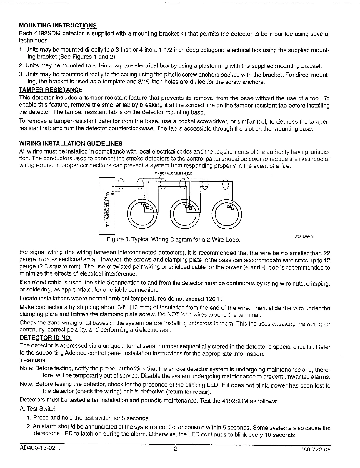
om,oNKcmEsHIELo
—
Rgure 3. Typical Witing Diagram for a 2-Wire Loop.
A78- , %%0,
For signal wiring (the wiring between interconnected detectors), it is recommended that the wire be no smaller than 22
gauge in cross sectional area. However, the screws and clamping plate in the base can accommodate wire sizes up to 12
gauge (2.5 square mm). The use of tilsted pair wiring or shielded cable for the power (+ and -) loop is recommended to
minimize theeffects of electrical interference.
If shielded cable is used, the shield connection to and from the detector must be continuous by using wire nuts, crimping,
or soldering, as appropriate, for a reliable connection.
Locate installations where normal ambient temperatures do not exceed 120°F.
Make connections by stripping about 3/8 (10 mm) of insulation from the end of the wire. Then, slide the wire under the
clamping plate andtighten theclamping plate screw. Do NOT!o~p \\,ires around tha terminal.
Check the zone \viting of all bases in the system before installing etiectcrs ir,::
em. Tnis incidces che~tir.;:>+t;:ringtc;
continuity, correct polari~, andperforming adielectrictesi.
DETECTOR ID NO.
The detector is addressed via a unique internal setial number sequentially stored in the detector’s special circuits Refer
to the supporting Ademco control panel installation instructions for the appropriate information.
TESTING
Note: Before testing, notify the proper authorities that the smoke detector system ;s undergoing maintenance and, there-
fore, will be temporarily out of service. Disable the s),stem undergoing maintenance to prevent unwanted alarms,
Note: Before testing thedetector, check forthepresence of?heblinting LED. Ifitdoes not blink, power has been lost to
the detector (check the wiring) or it is defective (return for repair).
Detectors must be tested after installation and periodic maintenance. Test the 4192SDM as follows:
A. Test Switch
1. Press andhold thetestswitch for5 seconds.
2. An alarm should be annunciated at the system’s control or console within 5 seconds. Some systems also cause the
detector’s LEO to latch on during the alarm. Othemise, the LED continues to blink every 10 seconds,
AD400-13-02
2
156-722-05
 Loading...