LEO
.7,,-,
ED TEST
TCH
F
E
❑ n ~,
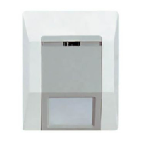
PUSH RECESSED SW~CH WITH
A ,1. MAX. DIAMETER TOOL
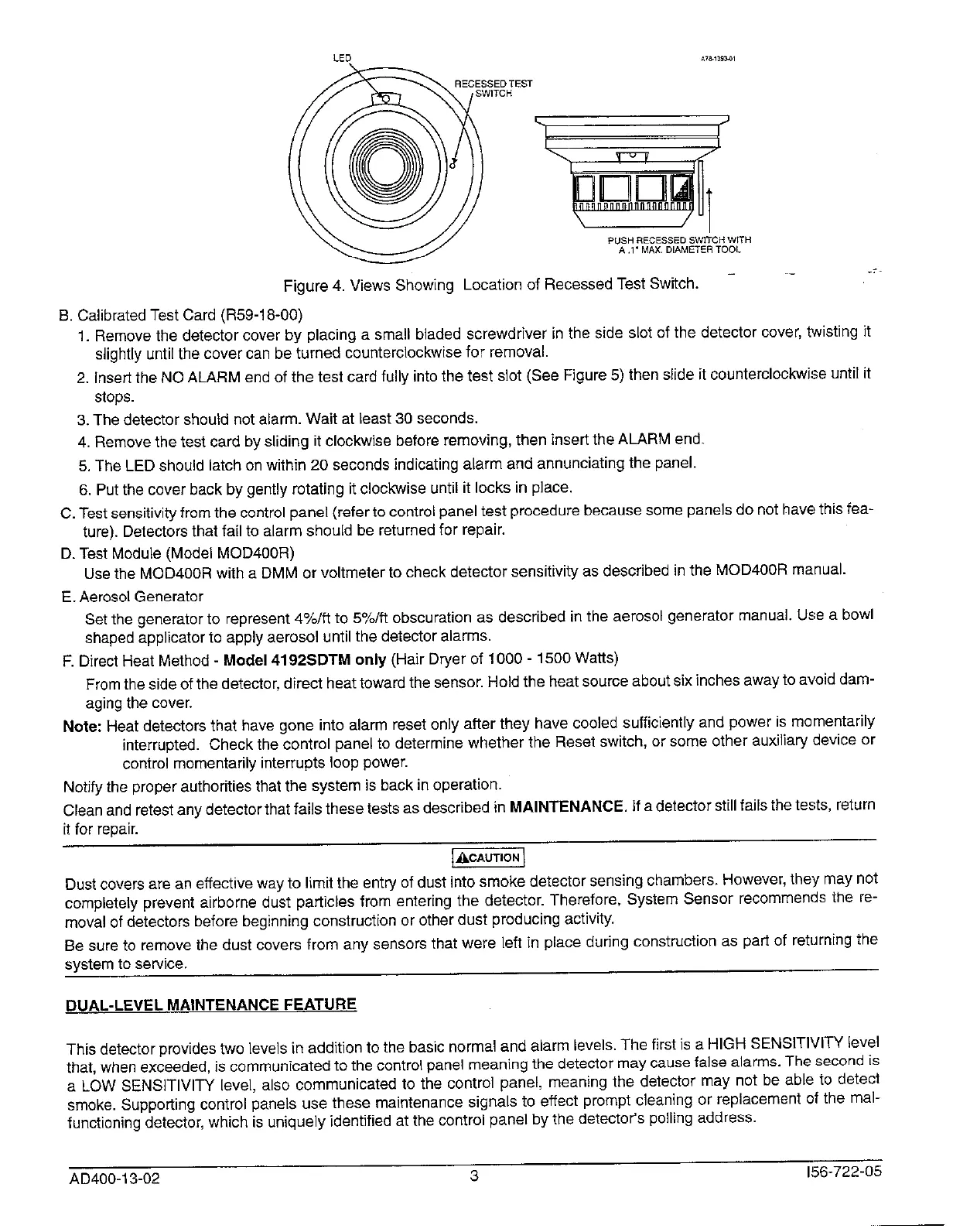
Figure 4. Views Showing Location of Recessed Test Switch. - ‘-
B. Calibrated Test Card (R59-1 8-00)
1. Remove thedetector cover byplacing asmallbladed screwdriver intheside slot of thedetector cover, tistingit
slightly until the cover can be turned countercloc~se for removal.
2. insert the NO ALARM end of the test card fully into the test slot (See Fqgure 5) then slide it counterclockwi!je until it
stops.
3. The detector should not alarm. Wait at least 30 seconds.
4. Remove the test card by stiding it clockwise before removing, then insert the ALARM end.
5. The LED should latch on within 20 seconds indicating alarm and annunciating the panel.
6. Put the cover back by gently rotating it cloc~se until it locks in place.
C. Test sensitivity from the control panel (refer to control panel test procedure because some panels do not have this faa-
ture). Detectors that fail to alarm should be returned for repair.
D. Test Module (Model MOD400R)
Use the MOD400R with a DMM or voltmeter to check detector sensitively as described in the MOD400R manual.
E. Aerosol Generator
Set the generator to represent 4Y./ft to 5Y~/ff obscuration as described in the aerosol generator manual. Use a bowl
shaped applicator to apply aerosol until the detector alarms.
F. Direct Heat Method - Model4192SDTM only (Hair D~er of 1000- 150CIWafts)
From the side of the detector, direct heat toward the sensor. Hold the heat source about six inches away to avoid dam-
aging the cover.
Note: Heat detectors that have gone into alarm reset only after they have cooled sufficiently and power is momentarily
interrupted. Check the control panel to determine whether the Reset switch, or some other auxiliary device or
control momentarily interrupts loop power.
Notify the proper authorities that the system is back in operation.
Clean and retest any detector that fails these tests as described in MAINTENANCE. If a detector still fails the tests, return
it for repair.
=
Dust covers ara an effective way to limit the entry of dust into smoke detector sensing chambers. However, they may not
completely prevent airborne dust particles from entering the detector. Therefore, System Sensor recommends the re-
moval of detectors before beginning construction or other dust producing iictivify.
Be sure to remove the dust covers from any sensors that were left in place during construction as part of ret{] rning the
system to sewice.
DUAL-LEVEL MAINTENANCE FEATURE
This detector provides two levels in addition to the basic normal and alarm levels, The first is a HIGH SENSITIVITY level
that, when exceeded, is communicated to the control panel meaning the detector may cause false alarms. The second is
a LOW SENSITIVIV level, also communicated to the control panel, meaning the detector may not be able to detect
smoke. Suppoting control panels use these maintenance signals to effect prompt cleaning or replacement of the mal-
functioning detector, which is uniquely identified at the control panel by thf? detector’s polling address.
—-
AD400-I 3-02 3
156-722-05
 Loading...