2
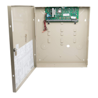
3. Mount the magnet (using the screws supplied) to the
wall, adjacent to the case, between the tamper position
indicator lines as shown in figure 4.
Verifying Tamper Operation (if used)
1. Plug the 5800WAVE into the AC receptacle. Wait until
the yellow LED turns off and clear any tamper fault
caused by the 5800WAVE from the control.
2. Unplug the 5800WAVE from the AC receptacle and
verify that the control now indicates the tamper fault.
Completing Installation
1. Remove the screw that secures the cover plate to the
duplex receptacle. Leave the cover plate in place on the
receptacle as shown in figure 5.
2. Plug the 5800WAVE back into the AC receptacle.
3. Insert the hold down screw (supplied) in the
5800WAVE mounting hole and secure the case to the
receptacle as shown in figure 5.
Note
: The mounting screw cannot be used in C-UL
installations.
4. When the yellow LED turns off, arm the control and
verify that the red LED turns on. Then disarm the
control.
5. With the control in the TEST Mode, test the
5800WAVE sounder by causing an alarm.
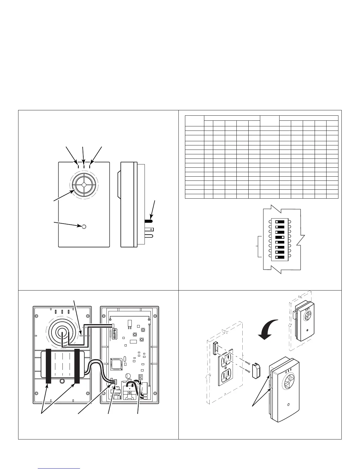
5800WAVE-001-V0
RED
LED
YELLOW
LED
GREEN
LED
SIREN
OUTLET
INDEXER
MOUNTING
HOLE
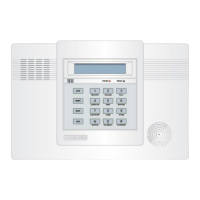
DIP SWITCH POSITIONS DIP SWITCH POSITIONS
House
ID
4 5 6 7 8
House
ID
4 5 6 7 8
0 – – – – – 16 ON – – – –
1 – – – – ON 17 ON – – – ON
2 – – – ON – 18 ON – – ON –
3 – – – ON ON 19 ON – – ON ON
4 – – ON – – 20 ON – ON – –
5 – – ON – ON 21 ON – ON – ON
6 – – ON ON – 22 ON – ON ON –
7 – – ON ON ON 23 ON – ON ON ON
8 – ON – – – 24 ON ON – – –
9 – ON – – ON 25 ON ON – – ON
10 – ON – ON – 26 ON ON – ON –
11 – ON – ON ON 27 ON ON – ON ON
12 – ON ON – – 28 ON ON ON – –
13 – ON ON – ON 29 ON ON ON – ON
14 – ON ON ON – 30 ON ON ON ON –
15 – ON ON ON ON 31 ON ON ON ON ON
“–“ Indicates “OFF.”
234561 78
ON
OFF
5800WAVE-005-V0
SWITCHES 1,2,3
MUST BE SET TO OFF
HOUSE ID 16 SHOWN
Figure 1. 5800WAVE Siren Module
Figure 3. DIP Switch Settings
234561 78
ON
OFF
5800WAVE-004-V1
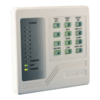
SIREN WIRE
HOLD DOWNS
BATTERY
JUMPER
(DO NOT REMOVE)
BATTERY
CONNECTOR
BATTERY
CLIPS
TERMINAL BLOCK
(NOT USED)
+
+
5800WAVE-003-V0
TAMPER
POSITION
INDICATOR
LINES
Figure 2. Battery and Siren Connection Points
Figure 4. Optional Tamper Magnet Installation