3.
Break out one of the two knockouts
that have been
provided for wire access (see Figure 3), and pass the wires
into the base of the PIR.
Caution:
Be certain that wires do not
obstruct the detector’s field of view.
4.
Connect all wires
to the screw terminals (see Figure 3 for
wiring details). Seal all openings in the base with foam or RTV
(not supplied) to prevent drafts or insects from entering the
unit.
5. For walk-test purposes, initially set the LED to “on” (jumper
removed), and set Pulse Count “off” (jumper removed).
6.
Mount the PIR base
to the ceiling with two screws, using the
screw holes provided in the base of the PIR.
Important Note:
Optimum mounting orientation is shown in
Figure 1. Mount the PIR in such a manner that the likely path of
an intruder is in the direction shown. This will ensure maximum
effectiveness of the Alternate Polarity feature.
RELAY
12V
LED
ALARM
DET
ON
PULSE
COUNT
LED
OFF
INTRUDER'S MOST LIKELY
DIRECTION OF MOTION
Figure 1. Optimum Mounting Orientation
LED ENABLE/DISABLE
The detector is shipped with the Alarm LED disabled (LED
enable/disable plug in place). The LED should be enabled (for a
walk-test) by
removing
the LED enable/disable plug (see Figure 3
for location). To prevent the loss of the plug, we suggest you
install it on one pin when the plug is not in use. When the walk-
test is completed, the LED may be disabled, if desired (plug in
place).
The LED may also be controlled from a remote location, as
follows:
Remove the LED enable/disable plug. Connect a switched line to
the upper pin (#1) of the two LED pins that can be grounded or
opened (see Figure 2). Grounding pin #1 will disable the LED.
Disconnecting it from ground will enable the LED.
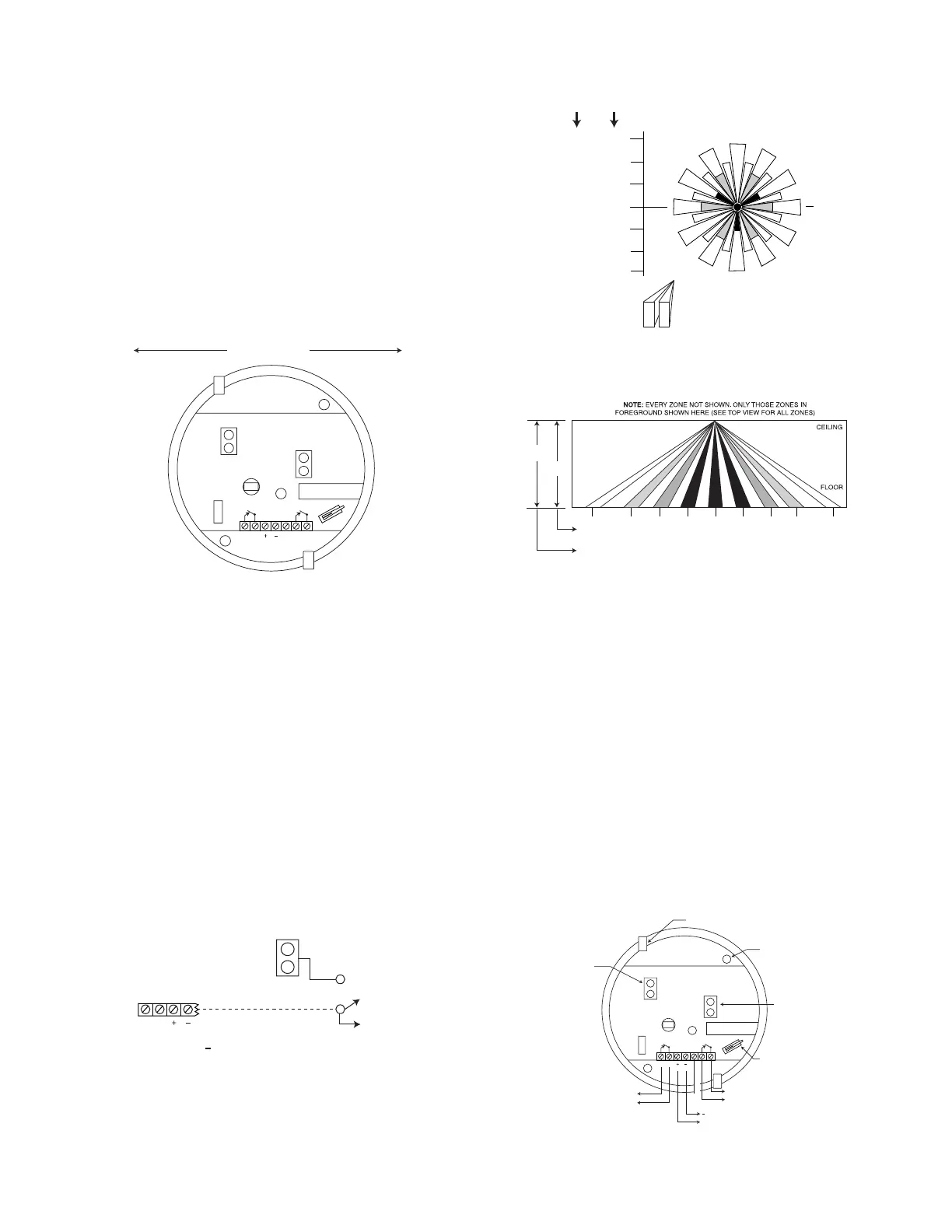
Detection Area – Optional 997WD Lens
(Lens available only outside of the U.S.A.)
TOP VIEW
RELAY
12V
1 LED
ENABLE
DISABLE
TO A GROUND TERMINAL ON
THE ASSOCIATED CONTROL OR TO
( - ) TERMINAL ON DETECTOR
Figure 2. Remote Control of LED
ZONES A CENTER ZONE
ZONES B (6 ZONES)
ZONES C (12 ZONES)
ZONES D (12 ZONES)
22 ft
(6.7m)
27.5 ft
(8.4m)
0
10 ft
HEIGHT
(3.1m)
8 ft
HEIGHT
(2.4m)
NOTE: EACH ZONE
CONSISTS OF TWO
FIELDS (INCLUDING
THE CENTER ZONE)
ZONES E (12 ZONES)
22 ft
(6.7m)
27.5 ft
(8.4m)
SIDE VIEW
13 ft
(4m)
7 ft
(2.1m)
3 ft
(0.9m)
22 ft
(6.7m)
16.25 ft
(4.95m)
8.75 ft
(2.67m)
3.75 ft
(1.14m)
27.5 ft
(8.4m)
0
13 ft
(4m)
22 ft
(6.7m)
16.25 ft
(4.95m)
27.5 ft
(8.4m)
3 ft
(0.9m)
3.75 ft
(1.14m)
7 ft
(2.1m)
8.75 ft
(2.67m)
10 ft
(3.1m)
8 ft
(2.4m)
EDCBA B
C
DE
TAMPER SWITCH
This PIR is equipped with a cover tamper switch. With cover
on, the switch is closed; when cover is removed, the switch
opens. The tamper terminals (see Figure 3) should be
connected to the control panel’s tamper loop.
PULSE COUNT OPTION
Each detector includes Pulse Count circuitry that is designed to
provide stability in adverse environments to minimize false
alarms. Two-event pulse count is provided by positioning the
jumper plug across the pulse count pins (see Figure 3 for
location). To select one-event pulse count (instant response),
remove the jumper plug. When programmed for 2-event pulse
count, the detector will signal an alarm within 3 or 4 steps,
since the processing logic requires more complex motion than
just a momentary event. When the detector verifies an
intrusion, the LED will light and the alarm relay contacts will
transfer, both conditions lasting for approximately 1 to 3
seconds (dependent upon signal strength).
To prevent the loss of the plug, we suggest you install it on one
pin when the plug is not in use.
RELAY
12V
LED
DET
LED
OFF
ALARM
NOT USED
TO CLOSED CIRCUIT
PROTECTIVE LOOP
- TO 12VDC
+ POWER SOURCE
TO SEPARATE
TAMPER CIRCUIT
TAMPER SWITCH
(OPENS WHEN
COVER IS
REMOVED).
LED.
"OFF" WITH PLUG
INSTALLED. "ON"
WITH PLUG
REMOVED.
MOUNTING
HOLES (2)
KNOCKOUTS (2)
FOR WIRE ENTRY
PULSE COUNT
"ON" WITH PLUG
INSTALLED."OFF"
WITH PLUG
REMOVED.
ON
Figure 3. PC Board (in base of PIR)
2
 Loading...