PowerLab Teaching Series - Owner’s Guide
30
The Analog Inputs
PowerLab input amplifiers have been designed with a considerable amount of
computer-controlled gain (up to × 2000). Thus it is possible to record a variety of signals
without any external pre-amplification. Each analog input is a separate DC amplifier with
programmable gain able to be set independently (the gain is set through the so ware
range control). The PowerLab inputs can be set by the so ware to be either single-
ended or di erential. In the di erential setting, the amplifier measures the di erence
between the positive and negative inputs, irrespective of ground.
It is important to note that the PowerLab grounds the inputs to amplifiers not in use.
It also grounds each amplifier and measures the DC o set voltage when the gain is
changed. In this way, the so ware corrects for any DC dri or o set in the circuits that
may develop over time or between readings.
Input impedance is one megohm. (On the 15T and /26 model PowerLabs, the impedance
between the earthing stud (ground connection) and the input connector grounds is
close to zero.
The Analog Outputs
The analog outputs provide computer-controlled variable outputs (±10 V) that can be
used with the LabChart and Scope applications either directly as a stimulator, or to
control peripheral devices. All stimulation voltage is generated by the PowerLab via the
output sockets on the front of the PowerLab (marked Output + and –), giving positive,
negative, di erential, depending on the sockets used and the so ware settings.
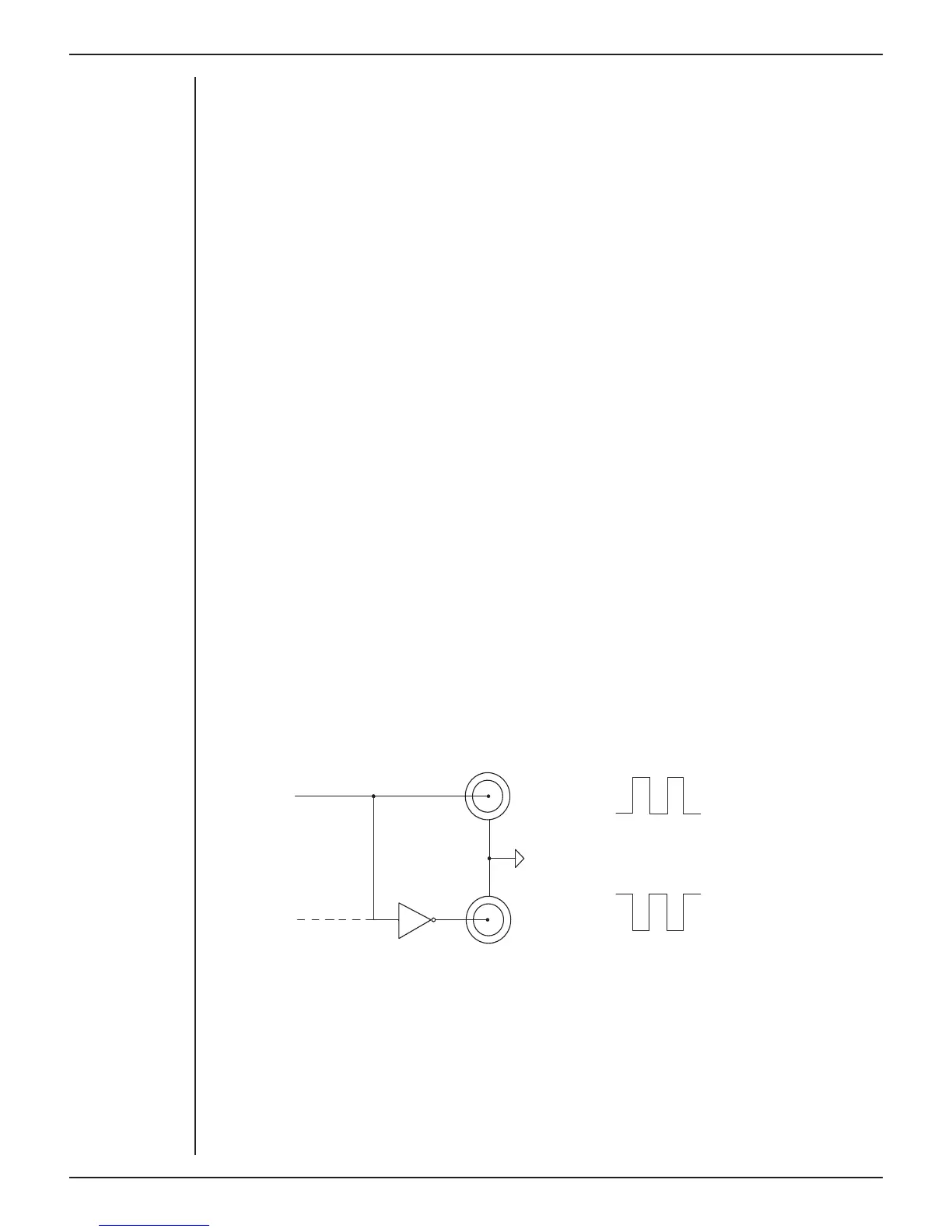
By default, the outputs are used for complementary (di erential) stimulation, where
Output + is positive and Output – is negative. When Output + is used, a positive stimulus
voltage (set up in LabChart or Scope) gives a positive voltage output, and a negative
voltage a negative one. When Output – is used, the voltage outputs are inverted. When
both output sockets are used, the stimulus is the di erence between the voltages at the
positive and negative outputs: you could generate up to a 20-volt pulse, given a ±10 V
range setting.
Figure 4-2
The analog output
stage, set up for a
di erential stiimulus
WARNING:
Analog outputs are
not to be used for
connection to
human subjects.
CAUTION:
Applying more than
±15 V to
the input can damage
the input circuits.
From DAC
+
-
+10V
-10V
+10V
-10V
GND
 Loading...