General
1. Please read
the
present
instructions carefully
and
observe
the
re-
commendations.
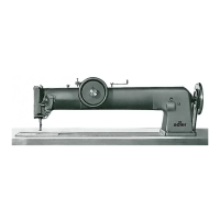
2.
The
following
text
applies
only
to
the
basic
operation
of
the
Adler
30.
If
operation
of
the
sub-classes differs
from
that
of
the
basic design, please see
the
attached
supplementary
instructions.
3.
The
different
languages have
been
marked
on
the
sheet
margin
by
the
respective letters:
D German
E English
F
French
S Spanish
Please
unfold
the
table
of
illustrations
at
the
end
to
the
right
so
that
you
can
see simultaneously
the
text
and
the
illustrations.
4.
In
order
to
extend
the
life
of
the
machine
the
maximum
sewing
speed
should
be
reduced in following cases:
During
the
running-in period
In
the
case
of
thick
material
When in
continuous
use
When using long stitches
When difficult
operations
are
involved
Operating elements
1
Thread
guide hole
2
Thread
take-up lever
3 Adjusting screw
for
take-up
lever
4 Scale
for
material thickness
5
Thread
reel pin
6 Handwheel locking
button
7 Handwheel (fixed
on
the
right
on
the
arm
shaft
when using a
stop
motor)
8 Bibbin winder
9 Hinged
throat
plate
10
Rotary
top
feed
foot
11
Stitch
regulator scale
12
Slight
for
adjusting
the
stitch
length
Unpacking
13 Wing handle
for
changing
the
direction
of
sewing
14 Sewing
foot
lifter
lever
15 Wing screw
for
the
adjust
·
ment
slide
of
the
stitch
regulator
16 Needle
threat
tension
17
Thread
guide
18
Thread
guide
19
Thread
guide
pin
21
Pushbutton
for
swinging
out
the
throat
plate
22
Sewing
foot
fastening
screw
1. Check
the
packing
for
damage in
the
presence
of
the
carrier
.
2. Check sewing
machine
,
stand
and
accessories
for
any
possible
transport
damage.
3.
Immed
i
ately
notify
any
damage in
the
presence
of
the
carrier
Assembly
1. Check
the
stand
designation.
2. Fasten
the
sew
ing machine
to
the
stand
by
screws
according
to
figs.
11-13
. These illustrations serve as
mounting
instruc
-
tions
and
show
how
the
respective assembled
stands
should
look like.
3. Place
the
driving
belt
on
the
sewing machine driving
pulley
and
place
the
small
stand
flywheel
100
, figs.
11
and
12
.
4.
Tension
the
V-belt as required as swinging
out
the
motor.
Cleaning and oiling
1. Depress
the
push
button
21,
fig. 1 . Swing
the
throat
plate
9
to
the rear.
2. Using a
clean
cloth
, remove anti-corrosion grease
and
dirt
from
all
components
.
3.
Oil all lubricating
points
marked
by
arrows in figs. 3
and
4 .
4.
Use
our
oil with following
propert
ies:
Viscosity
at
40°
C
cSt
:
65;
E = 8.6
Viscosity
at
50°
C
cSt:
42;
E = 5.6
Ref. No.
990
47
012
8
for
1 litre
container
Ref. No.
990
47
012
9
for
5 litre
container
.
Threading the needle thread
1. Pass
the
needle
thread
from
the
reel as
shown
in fig. 2.
2. When passing
the
thread
through
the
needle
bar
hole 1 place
the
about
25
cm
long
thread
end
in
the
threading wire sup-
plied
with
the
standard
accessories
and
pass
the
wire
through
the
hole
downwards.
Then
hold
fast
the
needle
thread
, pull
back
the
threading
wire
and
proceed
as shown in fig. 2.
Needle and thread
1. Use
tor
Adler
30
-
10
the
needle
system
332
Land
for
Adler
30-50
and
30-70
the
needle system
332
LLG.
2. General rule
for
needle size:
If
the
thread
jams in
the
Jong groove use a thic)ser needle.
If
the
thread
has
too
much clearance in
the
long groove use
a
thinner
needle.
3 . Match
needle
thread
to
mater
ial thickness
and
use left-torsion
threads. Right-torsion
threads
w
il
l
not
produce
so nice
stitches
4 .
The
bobbin
thread
should
be
thinner
or
softer
than
the
needle
thread.
Replacing the needle
1.
Conduct
the
needle
bar
to
its
topmost
position.
(Turn
the
side
handwheel
clockwise.)
2. Loosen
the
screw
33,
fig. 9.
3.
Remove
the
needle
from
the
needle bar
by
pulling it
downwards
.
4.
Insert
new
needle
with
the
groove facing
to
the left
and
retigh-
ten the
screw
33.
Use correct needle hole
According
to
the
needle
thickness ei
ther
of
the
two
needle holes
in
the
pivot-mounted
throat
plate
can
be
used.
1.
For
thick
needles = large
stitch
hole
For
thin
needles = small
stitch
hole
2.
Depress
the
pushbutton
21, fig.
7,
and
turn
the
throat
pl
ate
until
the
appropriate
needle
ho
le is
underneath
the
needle.
Ensure
that
the
pin
34
snaps again in
the
hole
35
.
Replacing the sewing
foot
1.
Conduct
the
needle
bar
to
its
topmost
point.
2. Move
the
sewing
foot
lifting lever
14,
fig.
1,
(on
the
backside
of
the
machine)
to
its
upper
position.
3.
Loosen
the
screw
22
and
remove
the
sew
ing
foot.
4.
Secure
new
foot
in inverse order.
Removing
the
shuttle
1.
Move
the
needle
bar
to
its
topmost
point
by
turning
the
handwheel
(not
in machines
with
stop
motor.
Here
the
needle
stops
always
in its
upper
position).
2. Depress
the
pushbutton
21, fig. 7
and,
at
the
same
time,
swing
the
throat
plate
9
to
the
l
eft.
3 . Remove
the
shuttle
36
.
Winding
the
bobbin thread
1. Pull
the
knurled
screw
6,
fig.
5,
forwards
and
turn
it
unt
il
the
pin rests,
the
machine
stops
and
the
handwhee
l runs idle.
In machines
with
stopmotor
the
handwheel
cannot
be
dis-
connected
.
The
sewing
mechan
i
sm
continues
operating.
2. Pass
the
bobbin
thread
from
the
reel
37,
fig.
5,
th
r
oug
h
the
thread
guide
38
,
3 . between
the
disks
of
the
tension
39
.
4 . Wind
the
thread
around
the
bobbin
40.
5 . Slip
the
bobbin
on
the
bobbin
winder
shaft
41.
6 . Loosen
the
screw
42,
swing
it
down
and
tighten
(in
th
is way
the
winder wheel will
be
pressed against
the
handwhee
l
and
will follow its
rotation).
7. By means
of
the
handle
101
turn
the
handwheel until t
he
bobbin
is
filled.
8 . Loosen
the
screw
42,
swing
it
upwards
and
tighten.
9 . Remove
the
filled
bobbin
.
Inserting
the
bobbin,
threading
the
bobbin thread
Small
shuttle
1.
Insert
the
bobbin
43
so
that
the
thread
is
unwound
as
shown
in fig. 6,
on
the
left.
2. Pass
the
thread
through
the
bobbin
slit
44
3.
into
the
slit
45,
4.
underneath
the
tensioning spring
46
and
5 .
approx
. 8
ems
through
the
hole
47
.
Large
shuttle
1. Insert
the
bobbin
48
so
that
the
thread
is
unwound
as
shown
in fig.
6,
on
the
right.
2. Pass
the
thread
through
the
hole
49
,
3.
underneath
the
tens
i
oning
spring 50,
4.
through
the
hole
51
and
5.
approx
. 8
ems
through
the
hole
52.
6.
Slip
bobbin
brake
sp
ring 53 over
the
bobbin (so
that
it
exerts
a slight pressure
on
the
latter).
Inserting the shuttle
1. Place
the
shuttle
36,
fig. 7,
into
its cage
and
place
the
protrud
,
ing
thread
end
to
the
rear
into
the
recess
54.
2. Depress
the
push
button
21
and
swing back
the
throat
plate
9
until
the
pin
34
engages (release
at
the
same
time
the
push
button
21
).
From the Library of Superior Sewing Machine & Supply LLC
 Loading...