cExpress-AL
Module Interfaces 31
4. Module Interfaces
This chapter describes connectors and pinouts, LEDs and switches that are used on the module but are not
included in the PICMG standard specification
4.1. Connector, Switch and LED Locations
LED1
4-pin
Fan
BIOS Defaults
RESET Switch
LED2
LED3
MIPI60
60-pin
to CPU
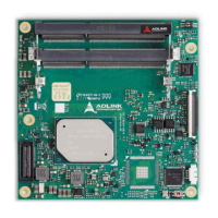
Figure 3: cExpress-AL Connector, Switch and LED Locations
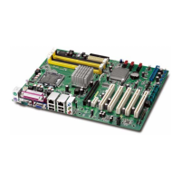
cExpress-AL and the DB40 Debug Module
For illustration purposes only
Figure 4: cExpress-AL and the DB40 Debug Module