Registers 21
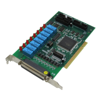
relay is open, the corresponding bit value read is ‘0’. If the relay is
closed, the bit value read is ‘1’.
3.4 Isolation Input Registers
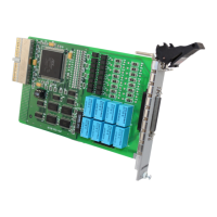
There are 8 isolated input channels on the PCI-7250 / 7251 board.
The status of the 8 channels can be read from the isolation input
register. Each bit corresponds to each channel. Bit value “1”
means input voltage is high and “0” means input voltage is low.
Note: Bits 8-15 are for cPCI-7252 only
Bit 7 6 5 4 3 2 1 0
Relay Output DO7 DO6 DO5 DO4 DO3 DO2 DO1 DO0
Output Readback RB7 RB6 RB5 RB4 RB3 RB2 RB1 RB0
Table 3-3: Data Format of Relay Output and Readback Status Registers
Bit 76543210
Iso. Input DI7 DI6 DI5 DI4 DI3 DI2 DI1 DI0
Bit 15141312111098
Iso. Input DI15 DI14 DI13 DI12 DI11 DI10 DI9 DI8
Table 3-4: Relay Output
 Loading...