6
7 8
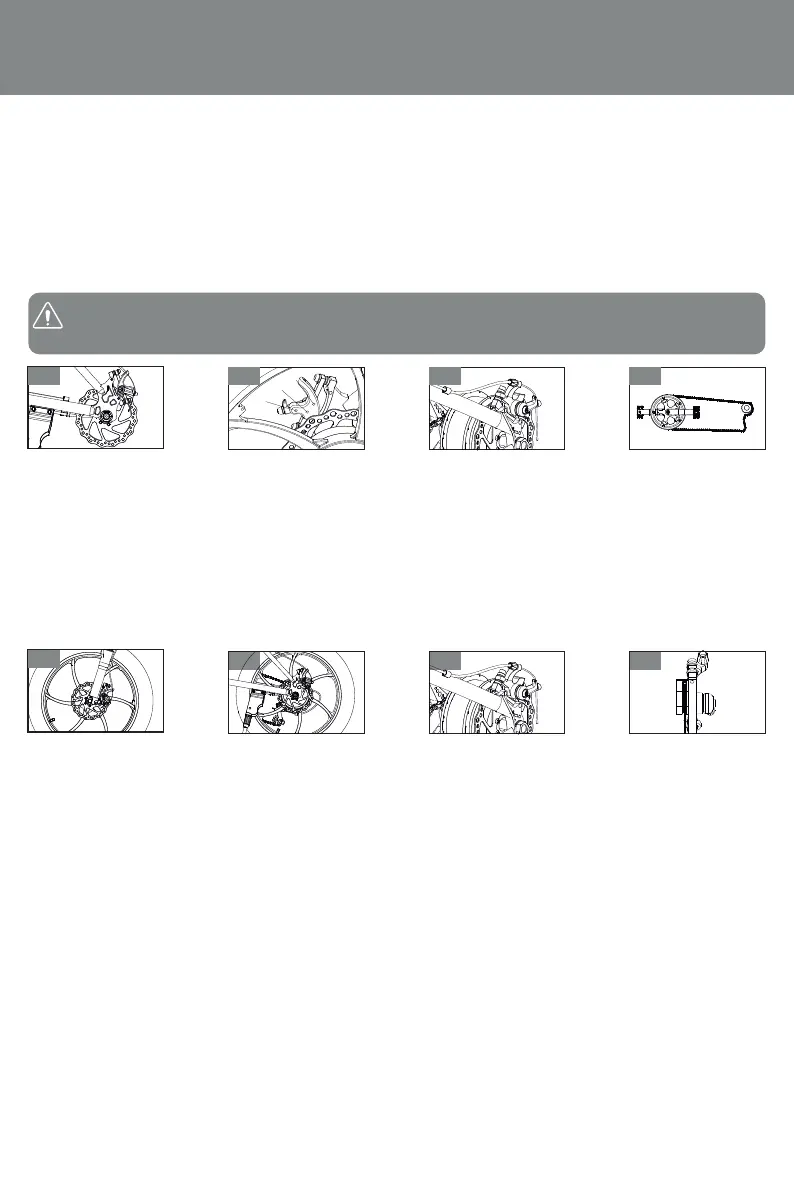
Adjustment methods of each part
I.Adustment of front and rear brae system: the adustment method of front and rear braes is the same
1.The rear integrated disc braesee gure 1 Adust the upper and lower nuts of the disc brae to mae the
spacing between disc brae and brae caliper 1.5-3mm, adust the height of disc brae, and then tighten the
nuts.
2.Front integrated disc brae see gure 2: Adust the A and B nuts of the disc brae and adust the height of the
disc brae so that the distance between the disc brae and the caliper is 1.5-3mm. If the distance is deviated, use
the C screw to adust, and then tighten the nut.
otate the Adusting nut to rotate the Adusting nut forward, the brae becomes tight, otherwise it becomes
loose. hen adusting, hold the brae handle at the same time, so that when the position of the brae handle is
1/3 of the total stroe, the brae rubber bloc can be tightly attached to the brae drum. ee gure 3
3.Disc brae: see Figure 7 and 8
ey points of disc brae adustment: there is enough clearance between disc brae and brae pad there is no
interference between the brae disc and the brae sin when rotating, and the best braing eect is appropriate
adust the nut, lengthen about brae cable, chec whether the brae handle has been adusted to the appropri-
ate tightness Then test ride to ensure eective and normal braing.
II.Chain adustment see gure 4
1.oosen the rear ale left and right fastening nuts, adust the chain regulator, move the rear wheels bac and
forth, and tighten the tightness of the chain so that the sag in the middle of the chain is 10-15mm.At this time,
the tightness of the chain should be suitable for go slic, no abnormal sound.
2.eep the center surface of the rear wheel basically in the center surface of the frame, and tighten the rear ale
left and right fastening nuts. ecommended torue is not less than 30N.m
III.Front wheel disassembly see Figure 5
1.oosen the left and rear fastening thread of the front ale, remove the nut, remove the front ale, and remove
the front wheel.
2.hen assembling, align the center hole of the front wheel with the double arm hole of the hydraulic front for,
penetrate the front ale into the hole, and tighten the left and right fastening nuts of the front ale cloc wise.
After installation, rotate the front wheel, and there shall be no stuc or loose phenomenon. The recommended
torue is not less than 18N. m
I.ear wheel disassembly see Figure 6
1.ull the motor cable o the connector, turn the car body overnote: Do not touch the handlebar, head cover,
toolbo parts, rotate the rear ale nut, rear brae positioning nut and brae cable in the counterclocwise
direction, unpac the chain oint, and then remove the rear wheel in the direction of the opening.
Note: To ensure driving safety, brae rubber the woring face is worn to 1/2 of brae rubber, a new brae
rubber should be replaced.
A
B
C
1
5
2 3 4
05