Do you have a question about the Ados GTR 210 and is the answer not in the manual?
Details the three available versions: GTR 210 Standard, GTR 210 EX, and GTR 210 Comfort.
Lists alternatives like IP 54 and IP 66 for different ambient temperatures.
Lists standards the GTR 210 conforms to, including EN standards for gas detectors.
Details standards for the Ex GTR 210, focusing on protection types and requirements.
Explains MED option compliance with directive 2014/93/EU and relevant ship standards.
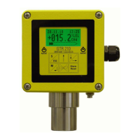
Describes the two-part housing, measurement cell, electronics, keyboard, and display.
Details sensor types used and how the sensor signal is processed and transmitted.
Provides recommendations for installing the transmitter in a suitable location.
Specifies the need for shielded cable and connection details for the signal line.
Lists common cable cross-sections and their maximum permissible lengths for supply lines.
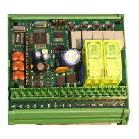
Module assembly and Connection details for 24V, 4..20mA, GND, PE.
Advises on replacing fuses with identical types, noting limitations for EX versions.
Terminal, Module assembly and Connection details for Comfort version.
Zero-potential change-over contact for alarms and fault.
Describes how to fit and secure the flow adapter to the gas transmitter.
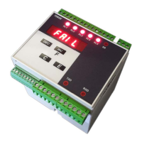
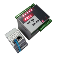
Connection to external control box for Power, Fault, Alarm, Buzzer, Button.
Green LED - Display Power supply, Yellow LED - Display Fault, Red LED - Display Alarm.
Emphasizes that the GTR 210 must be connected in a voltage-free status only.
Warns against installing standard and Comfort versions in Ex-zones.
Lists materials that can poison sensor elements, affecting accuracy.
Outlines the steps for commissioning after installation and connection.
Lists essential checks like calibration, signal transmission, and alarm triggers.
Explains the graphics display, status indicators, measured values, and bar graph.
Describes the meaning of different display colors and states (Normal, Alarm, Fault).
Details the function of each key (ESC, ENTER, UP, DOWN, Alarm Reset, Horn Reset).
Explains the three limit values that trigger alarms and their self-locking/acknowledgement options.
Describes how alarms are displayed and acknowledged, including horn relay options.
Lists the four available trend graph time scales (minutes, hours, days).
Explains how measuring ranges, overflow/underflow markings, and legal/illegal values are displayed.
Details the analogue output signal for transmitting measured gas concentration.
Specifies current output values for different states (fault, maintenance, normal) and fault relay status.
Describes the initial display screens and software version shown on startup.
Explains the self-test execution, parameter loading, and initial maintenance mode.
Explains the "VQ overload" exception state for pellistor sensors when values exceed 100%LEL.
Details how to end the sensor overload exception state using reset keys or digital input.
Lists the exception states: warm-up, calibration, parameterization, and fault.
Describes how warm-up, calibration, and parameterization exception states are reported.
Explains how to access the parameterization menu using the ESC key and code input.
Explains how to navigate menus, select items, and confirm/reject parameter changes.
The main menu consists of the sub-menu System, Sensor, Alarms, Calibration and the menu items Relay, Time/Date and Language.
This menu item is available in the comfort version of the GTR 210 only.
This item allows the user to enter the current date and current time.
This item is used to choose the language for the menu.
In this menu item the following information is output for the gas transmitter:
This sub-menu provides some self-test functions.
This menu item is used for checking the correct function of the relays.
With this function, the user can check the output current.
Using this function in the Comfort version of the GTR 210, the digital input can be tested.
The Watchdog is an important part of the equipment. It restarts the device within 1.6 s if the software fails.
This function is used to test the capacitive keyboard.
At this point, the correct function of the display can be checked.
All alarm changes are logged by the GTR 210. For each event that changes the alarm status...
Also, all faults occurring are logged by the GTR 210. As in case of the alarms...
Analog to the faults, access to the device parameters is saved.
With this sub menu it is possible to change the contrast of the display.
The sub-menu Sensor contains only the menu item History.
In the sub-menu Alarms, the limit values of the alarms, their monitoring direction...
First the monitoring direction for each limit can be selected.
When adjusting the parameters, any limit values less than 10% f.s.d....
This menu item is used for adjusting the parameters of the alarm self-locking facility.
The third limit value can be used for switching an acoustic warning device.
In the sub-menu Calibration, the gas sensor and also the output current are calibrated.
In the sub-menu Calibration, the gas sensor and also the output current are calibrated.
To calibrate the zero point, zero gas must be applied by way of a calibration gas adapter...
For calibrating the end value, test gas must be applied to the transmitter via a calibration adapter.
This menu item and the following item, are used for calibrating the output currents.
If the new calibration is outside the permissible range, the calibration is rejected with an error report.
In this menu item, the output current is calibrated.
If the new calibration is outside the permissible range, the calibration is rejected with an error report.
Lists all parameters, their adjustment range and default settings.
The default settings of the GTR 210 TOX O2 (measurement of oxygen) deviate as follows:
The following maintenance work refers to six monthly checks, which may only be carried out by trained personnel.
For safety-technical reasons, the sensing head should be checked once each year by a specialist.
The measuring device must have been in operation for at least two hours before the calibration of the gas sensor!
A suitable calibration gas adapter must be used for feeding the test gas.
In order to check the calibration of the zero point, zero gas (synthetic air in most applications) must be added...
In order to check the calibration of the end value, test gas must be supplied to the transmitter via the calibration adapter.
Calibration of the zero point is carried out in the menu under: Main menu => Calibration => Zero point.
After the time has elapsed, the GTR 210 waits for a user confirmation to check the new value...
Calibration of the end value is carried out in the menu under: Main menu => Calibration => End value.
The correlation between the test gas concentration and the concentration of the substitute gas can be derived from the following formula:
The output signals should be checked annually.
With the GTR210 Comfort, it should also be checked that...
Transmitter does not display anything: Power supply has failed / Fuses defective.
Output current cannot be calibrated: Supply voltage less than 18 V / Load impedance...
Error messages: I2C-Bus EEPROM, I2C-Bus RTC, Internal device error.
error message: overflow / -or- / error message: underflow
Dimensiones: GTR 210 with flow adapter (882-6266/b)
B134c
The following safe instrumented functions (SIF) of the gas measuring device are SIL1-capable:
The safety-related characteristic data only applies:
Reliability data for function 1 catalytic bead sensor
Reliability data for function 1 infrared sensor
Reliability data for function 2 (only available at Comfort-Version) catalytic bead sensor
Reliability data for function 2 (only available at Comfort-Version) infrared sensor
Reliability data for function 1 electro chemical sensor H2S
Reliability data for function 2 (only available at Comfort-Version) electro chemical sensor H2S
Covers supply voltage, power, outputs, operating conditions, and housing for standard version.
Details specifications for the GTR 210 Comfort version, including inputs and relays.
Lists supply voltage, operating conditions, and Ex certification for GTR 210 EX.
Compares technical data of semiconductor, pellistor, and thermal conductivity sensors.
Compares technical data of electrochemical, infrared, and photoionization sensors.
Lists measuring ranges and times for pellistor sensors with explosion protection.
Provides a list of tested substances, their lower explosion limits, and transmitter display values.
Lists available calibration and flow adapter accessories.
Lists available sensor types and photoionization detectors as spare parts.
| Brand | Ados |
|---|---|
| Model | GTR 210 |
| Category | Transmitter |
| Language | English |