Do you have a question about the Ados T060E PN Series and is the answer not in the manual?
Explains the manual's purpose and general usage guidelines.
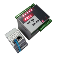
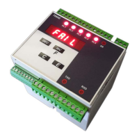
Details the weight transmitter's main features and characteristics.
Lists available options and how they are represented in the product model.
Outlines prohibited actions and essential safety precautions for operation.
Explains the meaning and purpose of various labels on the instrument.
Describes the power-on sequence and initial display indications.
Covers calibration, zero management, and signal filtering.
Explains calibration setup, sensitivity, and resolution settings.
Describes how to sum values from two channels for dual-channel systems.
Details how to reset potential zero deviations using external inputs.
Explains signal filtering methods for improving signal quality.
Details the instrument's front panel components and their functions.
Describes how weight values are displayed, including limits and special conditions.
Explains the meaning of the status LEDs on the front panel.
Details the operational purpose of each key on the front panel.
Covers common faults and troubleshooting steps, like cell connection errors.
Explains the FAIL signal for load cell connection issues and its impact.
Describes the configuration and operation modes of the instrument's relays.
Instructions for checking the received instrument and its included accessories.
General warnings and recommendations for safe installation of the unit.
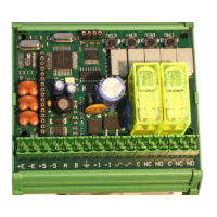
Notes that all instrument connections are made on the sides.
Mentions a label on the sides for easier cabling operations.
Advises verifying the voltage on the tag before connecting the power supply.
Details the wiring for connecting the power supply to terminal block B.
Wiring diagram for AC and DC power supply versions.
Wiring diagram for the 12-24V DC power supply version.
General guidelines for connecting load cells to terminal block A.
Specific wiring instructions for connecting the first load cell.
Wiring instructions for the optional second load cell input.
Provides an example diagram for a single weighing system setup.
Provides an example diagram for a double weighing system setup.
Details connecting RS232 and RS485 serial interfaces on side A.
Explains connecting digital inputs, such as for tare functions.
Details connecting the five SPST relay outputs on side B.
Describes the configuration and connection of the optional analogue output.
Shows the gateway and connections specific to the PROFINET interface.
States that no specific preventive maintenance operations are required.
Specifies that corrective maintenance must be performed by ADOS staff only.
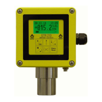
Introduces the instrument as a programmable unit adaptable to various applications.
Outlines the typical sequence of operations after connections.
Lists the main management functions: Configuration, Calibration, and Test.
Details how to access and select parameters for configuration.
Describes the procedure for editing parameter values using the instrument's keys.
Configures the sensitivity value of the connected load cells.
Sets the maximum capacity of the weighing system.
Defines the system's resolution based on capacity and divisions.
Configures digital filtering to reduce unwanted signal oscillations.
Selects the reference channel for dual-channel weighing systems.
Defines scale factors for adjusting channel values in dual-channel systems.
Assigns a specific function to relay 1 based on system events.
Sets the weight threshold value that triggers relay 1.
Sets the hysteresis value for relay 1 to prevent rapid switching.
Defines the minimum duration for an alarm condition to activate relay 1.
Sets the minimum time for relay 1 to return to its idle state.
Enables the FAIL function for channel 1 to manage fault conditions.
Enables the FAIL function for channel 2 to manage fault conditions.
Configures the operational mode for serial port 1 (e.g., excluded, continuous, Modbus).
Selects the physical interface for serial port 1 (RS485 or RS232).
Details the ASCII string format for continuous data transmission.
Sets the communication speed for serial port 1.
Assigns an address for multi-point RS485 network configuration.
Outlines the three key steps for configuring the analogue output.
Selects the output type: voltage (0-10V) or current (4-20mA).
Assigns the meaning to the analogue output signal (e.g., gross, net, total weight).
Defines the weight value that corresponds to the maximum analogue output signal.
Introduces the procedures for calibrating the weighing system.
Explains the general method involving applying known weights for calibration.
Details how to perform and store a permanent tare value.
Guides through the process of setting the zero point of the weighing system.
Explains how to set the full scale (span) of the weighing system.
Describes the process of linearizing the calibration curve using four points.
Details the three steps to adjust the analogue output signal accurately.
Guides the adjustment of the analogue output to represent zero accurately.
Guides the adjustment of the analogue output to represent the full scale accurately.
Provides functions to test the proper operation of instrument components.
Explains how to test the functionality of relay outputs and digital inputs.
Describes the procedure for testing the analogue output signal.
Explains how to test the signal received from the load cells.
Manages serial port configurations, including interface and communication modes.
Details the ASCII string format for continuous data transmission.
Explains the procedure for calculating the checksum for data integrity.
Details the string format used for bi-directional communication.
Describes the command structure used to request weight data.
Introduces the use of MODBUS RTU protocol for communication.
Explains how the instrument handles and responds to MODBUS exceptions.
Lists the available registers and their corresponding functions and types.
Explains the meaning of each bit within the instrument's status word.
Lists the supported coils for sending commands to the instrument.
Details data areas and registers specific to PROFINET communication.
Lists registers for input data within the PROFINET protocol.
Re-iterates the status word coding relevant to PROFINET.
Lists registers used for output commands in PROFINET communication.
| Brand | Ados |
|---|---|
| Model | T060E PN Series |
| Category | Transmitter |
| Language | English |