Do you have a question about the ADS P650.2 and is the answer not in the manual?
Guidance on how to use the manual for optimal installation and setup.
Warning about sustained listening to high volume levels and potential hearing damage.
Describes the high-efficiency, fast-overload recovery power supply.
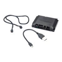
Highlights ease of installation with high-current speaker and power connectors.
Capability for dashboard-mounted subwoofer or rear channel level control.
Built-in high-pass, low-pass, and bandpass functions eliminating external networks.
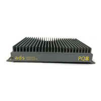
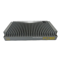
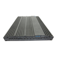
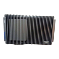
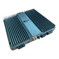
Original low profile, high efficiency heatsink design for space-saving mounting.
Allows connection to virtually any source unit from factory OEM to low output preamps.
Each channel pair can be used stereo, mono, or bridged for flexible speaker configurations.
Signal processing controls organized on one side for easy system adjustment.
Important safety precautions regarding battery, tools, fuses, and connections.
Guidance on under-seat mounting and required clearance for airflow.
Recommendations for vertical mounting and avoiding downward fin orientation.
Strong warning against installing the unit in the engine compartment due to heat/chemicals.
Details on minimum load impedance for stereo and bridged configurations.
Diagram for using the P450.2 in 4-channel mode with front/rear full range speakers.
Diagram for using the P450.2 in 2-channel bridged mode with full range speakers.
Diagram showing two P450.2 amps for tweeters/midrange and subwoofers.
Diagram for 6-channel use: front/rear speakers and subwoofers.
Diagram for 6-channel use: tweeters, midrange speakers, and subwoofers.
Diagram for 3-channel use: bridged front speakers and subwoofer.
Diagram for 6-channel use: front/rear speakers and bridged subwoofers.
Diagram for 8-channel use: tweeters, rear speakers, midrange, and subwoofers.
Diagram for 8-channel active mode: tweeters, midrange, midbass, and subwoofers.
Diagram for 4-channel bridged mode: front speakers and subwoofers.
Guidelines for using AWG #8 or larger cable, fuse placement, and capacitor use.
Diagrams and guidelines for connecting speakers in stereo configurations.
Diagrams and guidelines for connecting speakers in bridged configurations.
Connecting factory radio speaker outputs via mini-DIN adapter.
Connecting aftermarket sources using RCA cables to preamp outputs.
Routes RCA input from channels 1/2 to channels 3/4 based on switch position.
Selects input for channels 5/6 from summed RCA, 1/2 RCA, or 5/6 DIN/RCA inputs.
Selects input for channels 7/8 from summed RCA, 3/4 RCA, or 7/8 DIN inputs.
Independent level controls adjust input sensitivity from 100mV to 8V RMS.
Three-position switches for stereo, summed-bridged, or bridged-mono output.
Crossover selection for channels 1 & 2: output from 3&4, high-pass, or full range.
Dedicated crossover for channels 3 & 4; adjustable high-pass and low-pass for bandpass.
Crossover selection for channels 5&6: output from 3&4, low-pass, or full range.
Crossover section for channels 5 & 6; adjustable high-pass and low-pass.
Crossover selection for channels 7&8: output from 5&6, low-pass, or full range.
Troubleshooting steps for intermittent audio output issues.
Troubleshooting steps for audio distortion issues.
Troubleshooting steps for issues caused by shorted speaker wires.
Troubleshooting steps for issues related to improper internal crossover settings.
Details on power output, distortion, frequency response, and SNR.
Specifies the input impedance of the amplifier.
Lists the recommended fuse types for P850.2, P650.2, and P450.2.
Details on crossover adjustability and slope rates.
Physical dimensions for P850.2, P650.2, and P450.2 models.
| Channels | 2 |
|---|---|
| RMS Power @ 4 Ohms | 65W x 2 |
| Total Harmonic Distortion (THD) | <0.05% |
| Frequency Response | 10Hz - 40kHz |
| Dimensions | 228mm x 203mm x 54mm |