EasyManua.ls Logo

ADS P850.2 User Manual

Default Icon
26 pages
To Next Page IconTo Next Page
Page #1 background imageLoading...
Page #1 background image
table of contents
introduction 1
about this manual 2
features of your PowerPlate™ 2
warning and tips 3
mounting locations 3
system planning 4
system configurations 4-10
installation 11
controls and connections 11-12
signal sources 13-14
internal signal routing 14-15
multi-cross™ crossover and configurations 16-17
AC502 operation 18
tuning 18-19
P450.2 block diagram 20
P650.2 block diagram 21
P850.2 block diagram 22
troubleshooting 23-24
specifications 25
warranty information 26
introduction
Although it may be hard to remember, back in the 1970’s, car audio as we now know it didn’t really exist.
Sure, music lovers could buy a cassette or 8-track tape deck and some 6" x 9" three-way speakers.
Advanced stereo buffs might even add a "power-booster" to increase output too as much as 12 watts
RMS! But none of this really delivered the power to cut through road noise with sound quality that
compared with the best home audio. Not until 1979 that is, when a/d/s/ introduced the revolutionary
PowerPlate™ P100 amplifier and 300i 2-way plate loudspeakers. Aesthetically, the P100 introduced the
low profile design which has been an a/d/s/ trademark to this day. Technologically, the P100 combined a
high efficiency switching power supply with a state-of-the-art, discrete high-current stereo power
amplifier. For the first time, a car audio system existed with the musical integrity and dynamic range that
made you want to take long drives to nowhere, just to listen to the music. High quality car audio was
born, and the original a/d/s/ PowerPlate™ P100 made it happen.
The latest improvements to the PowerPlate™ line-up include increased heatsink area to facilitate higher
power output, and fully balanced high-level inputs compatible with any source. The amplifier you have
purchased is an enhancement of the respected P-series multichannel amplifiers. In this version, we have
improved upon the already acclaimed sound quality by addressing internal details, and upgrading selected
components to incorporate the latest technology which was not available when the P-series was originally
designed. Selected low-noise, high-speed op amps are used in critical circuits. Class-A biasing is used
throughout the voltage-gain and active crossover stages. Numerous modifications and "tweaks" were
also performed which improve the power supply dynamics and reduce noise. These changes improve
transparency and dynamic linearity, resulting in a smoother and more detailed top-end, tighter bass, more
explosive dynamic contrasts, and virtually holographic imaging. Left intact are the P-series unequalled
flexibility, high efficiency and superb reliability. These, along with multichannel design, are fundamental in
the a/d/s/ approach to systems engineering, which makes achieving true high fidelity reproduction simple
and predictable in any installation.
1
Question and Answer IconNeed help?

Do you have a question about the ADS P850.2 and is the answer not in the manual?

ADS P850.2 Specifications

General IconGeneral
Power Output850W
Frequency Response20Hz - 20kHz
Total Harmonic Distortion (THD)<0.05%
Channels2
Crossover Frequency50Hz
Bass Boost0dB
RMS Power @ 4 Ohms2 x 210W

Summary

PowerPlate™ Amplifier Introduction

PowerPlate™ Manual Overview and Safety

About This Manual

Explains the purpose and scope of the manual.

Safety First: Hearing Protection

Provides crucial safety advice regarding hearing protection from loud music.

Key Features of PowerPlate™

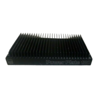
Details the key features and technological advantages of the PowerPlate™ system.

Installation Warnings and Mounting

General Warnings and Installation Tips

Provides essential safety warnings and practical tips for installation and use.

Mounting Locations for Amplifier

Discusses various suitable locations for mounting the amplifier in a vehicle.

System Planning and Configurations

Speaker Requirements for Amplifiers

Details the impedance requirements for connecting speakers to the amplifier.

System Configuration Examples

Presents common system configurations and their setup.

P450.2 System Diagrams

P450.2 System 1: 4-Channel Mode

Shows a 4-channel setup for front and rear speakers.

P450.2 System 2: 2-Channel Bridged Mode

Illustrates a 2-channel bridged setup for full-range speakers.

P450.2 System Diagrams (Continued)

P450.2 System 3: Dual Amplifier Setup

Depicts a system using two P450.2 amplifiers for tweeters, midrange, and subwoofers.

P650.2 System Diagrams

P650.2 System 1: 6-Channel Mode

Shows a 6-channel setup with specific crossover configurations.

P650.2 System 2: 6-Channel for Various Speakers

Illustrates a 6-channel setup for tweeters, midrange, and subwoofers.

P650.2 System Diagrams (Continued)

P650.2 System 3: 3-Channel Mode

Depicts a 3-channel setup for front speakers and a subwoofer.

P850.2 System Diagrams

P850.2 System 1: 6-Channel Mode

Shows a 6-channel setup for front/rear speakers and subwoofers.

P850.2 System 2: 8-Channel Mode

Illustrates an 8-channel setup for tweeters, midrange, and subwoofers.

P850.2 System Diagrams (Continued)

P850.2 System 3: Full 8-Channel Mode

Depicts an 8-channel setup with various crossover configurations.

P850.2 System 4: Bridged 4-Channel Mode

Shows a 4-channel bridged setup for speakers and subwoofers.

Installation and Connections

Installation Procedure

Guides the user through the step-by-step process of installing the amplifier.

Power Connections

Details the requirements and procedures for making power connections.

Speaker and Signal Connections

Speaker Connections

Explains speaker connections for stereo and bridged configurations.

Signal Sources Overview

Details how to connect different signal sources (OEM and aftermarket) to the amplifier.

Signal Sources

OEM Radio Integration

Explains connecting to OEM radios via a mini-DIN adapter.

Aftermarket Source Connections

Describes connecting aftermarket sources using RCA cables.

Internal Signal Routing

2-Channel/4-Channel Input Switch Function

Explains the function of the input switch for channel routing.

Internal Signal Routing (Continued)

Channels 5/6 and 7/8 Input Switches

Details input switches for channels 5/6 and 7/8 on specific models.

Level and Output Controls

Describes the function of level and output configuration controls.

Multi-Cross™ Crossover Configuration

Crossover Controls for Channels 1-4

Explains crossover selections for channels 1&2 and 3&4.

Crossover Controls for Channels 5/6 (P650.2)

Details crossover selections for channels 5&6 on the P650.2 model.

Multi-Cross™ Crossover Configuration (Continued)

Crossover Controls for Channels 5/6 (P850.2)

Details crossover selections for channels 5&6 on the P850.2 model.

Crossover Controls for Channels 7/8

Explains crossover selections for channels 7&8.

Tuning and Optional Accessories

Using the AC502 Remote Control

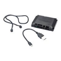
Covers the operation and integration of the optional AC502 remote control.

Tuning the Crossover Settings

Details how to adjust the crossover controls for optimal speaker performance.

Adjusting Input Sensitivity

System Diagrams: P450.2

System Diagrams: P650.2

System Diagrams: P850.2

Troubleshooting Common Issues

No Output and Audio Cycling

Addresses symptoms related to the amplifier having no output or cycling.

Distorted Output

Offers solutions for distorted audio output.

Troubleshooting Common Issues (Continued)

Poor Bass Response

Addresses issues with poor bass response in the audio system.

Fuse Blowing Issues

Provides troubleshooting for problems causing fuses to blow.

Specifications

Amplifier Section Specifications

Lists technical specifications for amplifier performance and power.

Crossover and Dimension Specifications

Details crossover capabilities and physical dimensions of the amplifier models.

Warranty Information

Limited Two-Year Consumer Warranty

Outlines the terms of the limited two-year consumer warranty.

Related product manuals