TSSC Installation and Setup Guide
STEP 1 - Installing the Base Rechargeable Backup Battery
and Power Connector
1. Remove the Base Case Back.
2. Connect the battery connector to the receptacle on the PC board.
3. Insert the Battery Pack into the case.
4. Secure the Battery Pack with the Battery Retainer using the Retaining Screw.
5. Connect the power pack into the power receptacle, looping the power cord as
shown in Detail A.
NOTE: If using the optional wall mount configuration, skip to the Base wall
mounting procedure. If not, complete step 6.
6. Secure the Case Back onto the Base.
NOTE: Do not apply power at this time.
Mounting the Base to a Wall (Optional)
To mount the Base to a wall, perform to the following:
IMPORTANT: Record the ACTIVATION KEY number, MAC Address, CRC
number and WPA2 number located on case back prior to wall mounting.
1. Complete steps 1 through 5 of the Installing the Base Rechargeable Backup
Battery and Power Connector paragraph
2. Secure the Mounting Plate to the wall and secure with 4 screws.
3. Install the Tamper Screw as shown.
4. Secure the Base to the Mounting Plate by aligning the slots on the Base and
sliding the unit down until locked in position.
STEP 2 - Setting up the Communication Links
Prior to power up of the Base (when directed in the TSSC Installer App), the
Ethernet communications link must be connected to the residence’s router. The
connection is from an Ethernet port on the router to the “BROADBAND” port on
the Base.
IMPORTANT! Under no circumstances should the “DEVICE LAN” port ever be
connected to the residence’s router.
Ê800-13956V1oŠ
800-13956V1 11/13 Rev. C
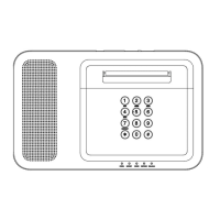
STEP 3 - Keypad Mounting
The keypad is designed to be placed on a desk/table top with the stand attached.
An optional mounting plate can be used to mount the keypad to the wall.
Power Connections
Connect the Power Supply Cable into its connector as shown below and route it
from the bottom of the keypad.
IMPORTANT: Do not apply power to the keypad at this time.
Installing Keypad To Desk-Top Stand
1. Place the Keypad face down on a level surface.
2. Connect the battery connector to the receptacle on the PC board.
3. Insert the Battery Pack into the case.
4. Secure the Battery Pack with the Battery Retainer using the Retaining Screw.
5. Install tabs on Desk Stand into appropriate slots as shown and secure with
two screws
6. Plug in the power pack to the receptacle.
STEP 4 - Base Registration & Accessing the Installer App
Run TSSC Installer App:
Go to https://portal.adtpulse.com/activation/access/signin.jsp and follow the
prompts.
Power the Base Unit
When directed in the TSSC Installer App, plug the power pack into the wall
receptacle to power the Base. During the first 45 seconds of power initialization,
TSSC lights up the CELLULAR, NETWORK and STATUS LEDs one by one
slowly in sequence. After the first 45 seconds, the LEDs chase in a rapid sequence
for approximately 30 more seconds. The POWER LED is always ON while
initialization is being executed. When the LEDs stop chasing and the POWER
LED is lit green, the Base is powered up and ready for the registration process to
begin.
NOTES: • The BATTERY LED will blink until the battery is fully charged.
• The NETWORK LED will remain amber until activated.
IMPORTANT: Once the programming procedure has started and the unit
is powered up, do not remove power or disconnect the battery, nor open
the case. Disconnecting power or activating the tamper switch can cause
unpredictable programming results.
POWER DOWN CAUTION: To power down the system, do the following:
1. Clear the alarm memory.
2. Enter “MASTER CODE + [#] + [∗] + 9” at the TSSC Base unit, then wait until
the four LEDs to the right of the Power LED turn off before removing power.
IMPORTANT: Shutting down the Base unit will cancel the sending of any
reports to the central station that may be in progress.
Radio Activation
Go to https://3ps.adt.com and follow the prompts.
Testing the System
There are three test modes as follows:
Walk Test: user code + 5 + 1 (tests the sensors in the system; see User Guide for
details)
Comm Test: user code + 5 + 2 (tests the communication link)
NTP Server Test: user code + 5 + 3 (causes the panel to contact the NTP server to
verify that the communication link to the NTP server is valid)
Specifications
Base Unit:
Dimensions: .........................8.5” W x 6” H x 1.875” D
Voltage Input: ....................P/N 300-05763V1: 110 VAC input/9 VDC output 2.5A,
2-prong
24-Hour Backup Battery: ..P/N 300-03866: Rechargeable Backup Battery: Nickel-
metal hydride battery pack rated at 7.2 Vdc, 3700mA
Communication:
Formats Supported: ...........4-Digit Contact ID
Keypad:
Dimensions: .........................6.69” W x 5.36” H x 0.875” D
Voltage Input: ....................P/N 300-05763V1: 110 VAC input/9 VDC output 2.5A,
2-prong
24-Hour Backup Battery: ..P/N 300-06868: Rechargeable Backup Battery: 7.2V,
6xAAA, 6x600mAH, NiMH