Rack Installation
The RD-71 is intended to be mounted in a standard 19” rack. It occupies 1RU of rack space
and the connections are all on the rear of the unit.
To install the RD-71 into a rack use the following steps:
Determine the desired position in the rack for the RD-71 making sure that the
air intake and exhausts on the sides of the unit will not be obstructed.
Insert the rack mount clips into place over the mounting holes in the rack.
Slide the RD-71 into position in the rack.
Secure the RD-71 to the rack by installing four rack screws through the front
mounting holes and tightening.
If needed, secure a grounding wire use the grounding location on the rear
panel of the RD-71.
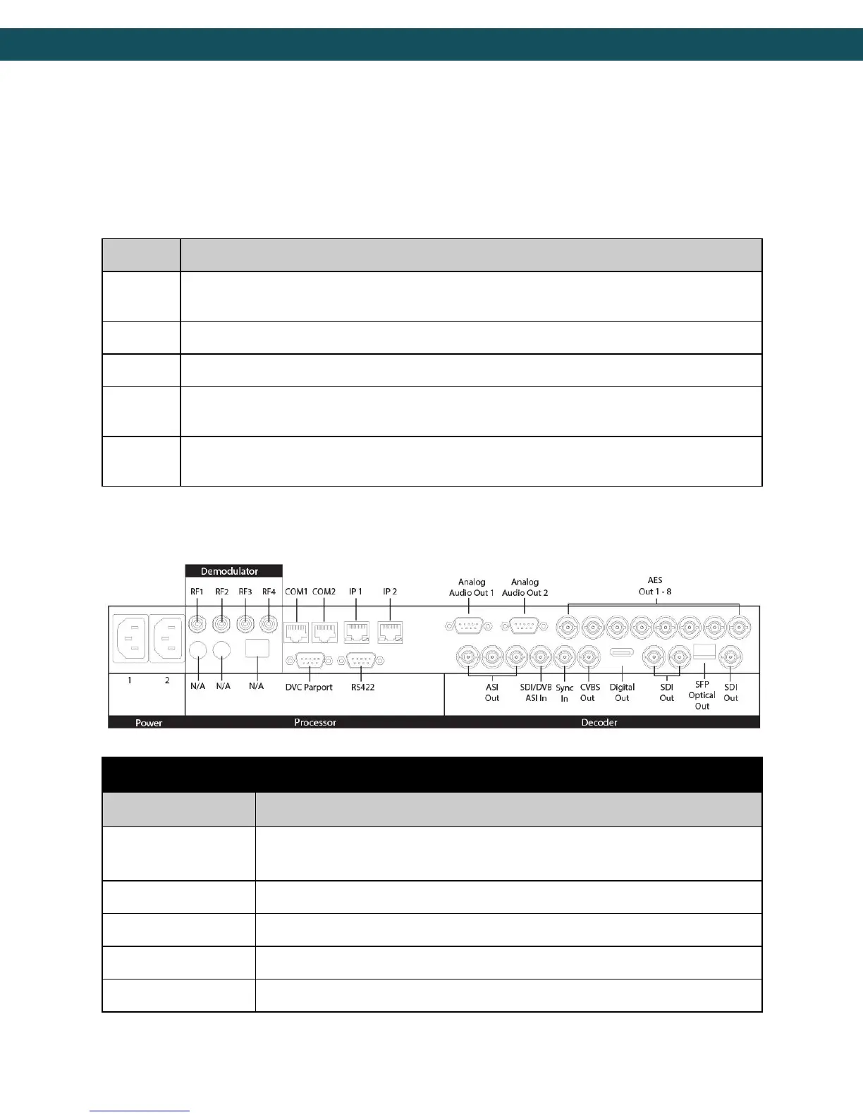
Back Panel
Redundant AC Power, Standard 3 pin computer power plug
(Auto range 70-240 VAC Input)
API Serial Communication Interface
Serial Port Used for Troubleshooting (Terminal)
Default Management/Monitoring interface (10/100/1000)
Default UDP/RTP transport interface (10/100/1000)
7