61287781F1-22D 3
Step 2: Connect POTS
If POTS cables are not available, use Figure 3 and the following
procedure to fabricate the POTS cables.
1. Trim the insulation for the subscriber POTS cables.
2. Refer to the illustration below and connect the twisted-pair
Tip (green) and Ring (Red) to the RJ-11 connector using an RJ-
11 crimper.
3. Insert the RJ-11 connector in the appropriate PHONE 1 or
PHONE 2 jack.
Figure 3. POTS (PHONE) Connection
Step 3: Connect Ethernet
The 424RG ONT supports four 1 Gigabit (10/100/1000Base-T)
connections (GE 1 to GE 4).
If Ethernet cables are not available, use the following procedure and
table to fabricate the Ethernet cables.
1. Trim the insulation for the subscriber Ethernet cable.
2. Connect the wires per the following table using an RJ-45
Crimper.
3. Insert the CAT 6 rated cable in the appropriate GE 1 through
GE 4 ports on the rear of the 424RG ONT.
Step 4: Connect Power
Plug the supplied 12 VDC Power Adapter into the 12V connection
on the rear of the chassis. Connect the AC plug to a standard 120
VAC outlet.
Step 5: Connect USB
There is a USB data connection on the rear of the 424RG ONT that
can be used for connection and communications with other
computers and electronic devices.
Ethernet RJ-45 Pin-out
Pin Name Description Color Code
1 TRD0+ Transmit/Receive Positive White/
Orange
2 TRD0- Transmit/Receive Negative Orange
3 TRD1+ Transmit/Receive Positive White/Green
4 TRD2+ Transmit/Receive Positive Blue
5 TRD2- Transmit/Receive Negative White/Blue
6 TRD1- Transmit/Receive Negative Green
7 TRD3+ Transmit/Receive Positive White/Brown
8 TRD3- Transmit/Receive Negative Brown
1 2 3 4
1 = Not Connected
2 = Tip
3 = Ring
4 = Not connected
Step 6: Connect UPS (optional)
DO NOT connect the Power Adapter and an UPS at the same time
as this will cause damage to the 424RG ONT. The ONT can be
powered by either power source, but not both simultaneously.
The 424RG ONT can typically use an un-interruptible power
supply (UPS) if desired. Power is supplied to the 424RG ONT by a
local power source with battery backup that utilizes the AC power
at the customer premises to charge the battery when it is not in use.
The UPS powers the 424RG ONT and functions as a BBU supplying
continuous 12 VDC. Refer to the installation material that is
provided with the UPS when installing the BBU.
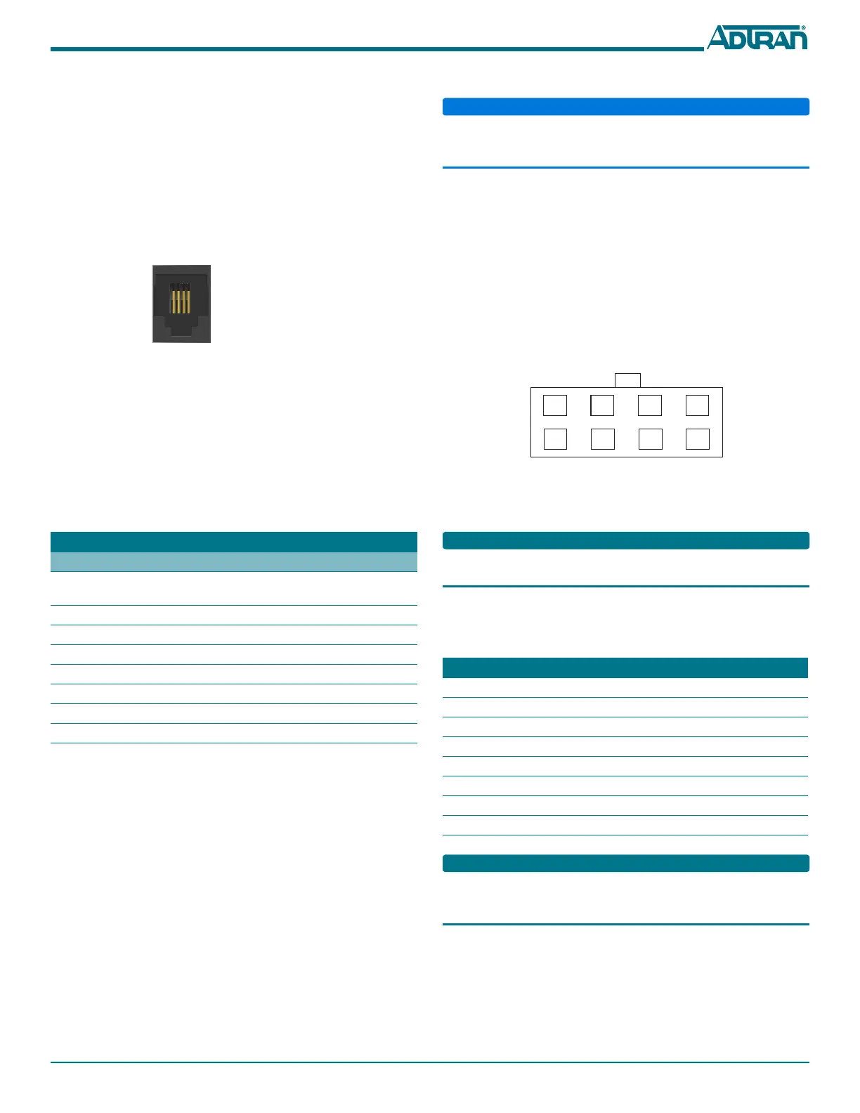
UPS Connector
Connect the UPS to the 8-pin MOLEX connector labeled “UPS”
located on the rear of the SFU ONT chassis. Figure 4 illustrates the
MOLEX connector on the rear of the ONT.
Figure 4. 8-Pin Molex Connector
The UPS Power/Alarm Connections Table below defines each pin
on the connector.
ADTRAN offers a UPS Cable assembly (P/N 1287402G1) for the
MOLEX connector.
UPS Power/Alarm Table
The following table indicates which pin is associated with each
alarm provided through a UPS connection.
If an UPS is being used and the battery is disconnected, the 424RG
ONT is not protected from power outages, and will send a “Battery
Missing” alarm to the OLT.
Pin-Out Description Alarm
1 Power Input (+12 VDC) -
2UPS Status - On Battery1
3 UPS Status - Battery Missing 2
4 Signal Return -
5Power 12 V Return-
6 UPS Status - Replace Battery 3
7 UPS Status - Low Battery 4
8 No Connection -
 Loading...