4 617600132F1-13A
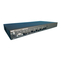
3. For a Voice connection on the 854-v6 only, insert an RJ-11 cable into one of the telephone ports (labeled Tel 1 or Tel 2) until there is an audible
“click”.
4. Before connecting to the service provider interface, clean the optical Interfaces of the SC/APC connectors.
5. Insert the fiber cable into the WAN port on the bottom of the gateway.
Connecting the Power Supply
1. Connect the end of the power adapter to the Power port on the rear panel of the gateway
2. Plug other end of the power adapter into the wall outlet.
3. Confirm that the power is connected properly. The Power LED should be lit on the front of the gateway.
Resetting the Gateway
A reset button is available if the device needs to be rebooted. To reboot the device, press the Reset button on the rear panel of the gateway for 5 seconds
or less. To reset the device to custom defaults, press the Reset button for 5 seconds or more.
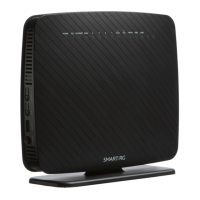
Understanding the Status LEDs
The LEDs on the back panel of the device enable you to monitor the device status. This section describes the four types of LEDs available on the
gateway. See Figure 3 for details.
Figure 3. Status LEDs
Fiber Status LED
The Fiber status LED indicates the state of an inserted Fiber SFP module.
2.5G WAN LED
The 2.5G WAN status LED indicates the state of the 2.5G WAN connection on the gateway.
CAUTION!
f
To prevent breaking the fiber, do not exceed the fiber bend radius of 3.5 in (8.9 cm).
NOTE
g
Alternately, the device may be powered by a supported third-party UPS which may be connected via 7-pin molex connector, labeled UPS.
LED Color State Description
Fiber
Green
On Fiber optic connection is UP.
Flashing Fiber optic connection is discovering or activating the ONT on the PON.
None Off Fiber optic connection is DOWN.
LED Color State Description
WAN
2.5.Gbps
Green
On WAN is UP at 2.5 Gbps speed.
Flashing WAN connection is transferring data.
1000/
100 Mbps
Orange On WAN is UP at 1000/100 Mbps speed.
Flashing WAN connection is transferring data.
None Off WAN connection is DOWN.

 Loading...