For more detailed documentation, visit us online at www.adtran.com
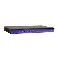
NETVANTA 5305 CONTROLLER P/N 1200831L1
Quick Start Guide
Quick Start Guide, 61200831L1-13B, July 2004 Technical Support 1-888-4ADTRAN (1-888-423-8726) © 2004 ADTRAN, All Rights Reserved
ETHERNET PINOUT
Pin Name Description
1 TX1 Transmit Positive
2 TX2 Transmit Negative
3 RX1 Receive Positive
4, 5 — Unused
6 RX2 Receive Negative
7, 8 — Unused
CONSOLE PINOUT
Pin Name Description
1 DCD Data Carrier Detect (output)
2 RD Receive Data (output)
3 TD Transmit Data (input)
4 DTR Data Terminal Ready (input)
5 SG Signal Ground
6 DSR Data Set Ready (output)
7 RTS Request to Send (input)
8 CTS Clear to Send (output)
9 RI Ring Indicate (output)
INSTALLATION INSTRUCTIONS
1. Remove the existing controller from the controller slot in the NetVanta 5305
Base Unit.
2. Slide the System Controller into the controller slot until the module is firmly
positioned in the chassis.
3. Secure the screws at both edges of the module. Tighten with a screwdriver.
4. Connect the cables to the associated device(s).
5. Complete the system installation as specified in the Hardware Installation
Guide (P/N 61200990L1-34).
SPECIFICATIONS
Interfaces: Console: EIA-232 (DB-9 female) for access to command line
interface and monitoring
Ethernet: Two 10/100BaseT interfaces (RJ-48C) for
connection to the local area network
Compliance: FCC Part 15, Class A, UL 60950/CSA-C22.2 No. 60950,
EN 60950, IEC 60950, AS/NZS 60950, EN 55022, EN 55024
Environmental: Operating Temperature: 0°C to 50°C
Storage Temperature: 20°C to 70°C
Relative Humidity: 95% non-condensing