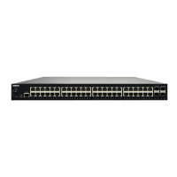
The NetVanta 1560-48-740W is a robust and versatile network switch designed to provide reliable and high-performance connectivity for various network environments. This device is engineered to support a wide range of applications, from small office setups to more complex enterprise networks, offering flexibility in deployment and management. Its comprehensive feature set ensures efficient data handling, power delivery, and network security, making it a valuable asset for modern IT infrastructures.
Function Description
The primary function of the NetVanta 1560-48-740W is to facilitate network connectivity and data transfer. It acts as a central hub, allowing multiple devices to communicate with each other and with external networks. The switch supports both standard Ethernet and Power over Ethernet (PoE) capabilities, enabling it to power compatible devices such as IP phones, wireless access points, and security cameras directly through the network cable. This eliminates the need for separate power outlets for these devices, simplifying installation and reducing cable clutter.
The device is equipped with multiple RJ-45 ports for standard Ethernet connections and SFP+ ports for high-speed fiber optic connections, providing options for various network topologies and bandwidth requirements. The SFP+ modules can be easily installed or removed without powering off the switch, allowing for flexible upgrades and maintenance.
Beyond basic connectivity, the NetVanta 1560-48-740W offers advanced configuration options through both a web-based Graphical User Interface (GUI) and a Command Line Interface (CLI). These interfaces allow network administrators to fine-tune network settings, implement security policies, and monitor network performance. The switch supports various network protocols and features, ensuring compatibility with existing network infrastructures and providing a scalable solution for future growth.
Usage Features
The NetVanta 1560-48-740W is designed for ease of use and flexible deployment. It can be mounted in a standard 19-inch rack, on a desk, or on a shelf, accommodating different physical environments. For rack mounting, the device includes mounting brackets that can be securely attached to the chassis and then to the rack posts. Desk or shelf mounting is also straightforward, requiring verification of the surface's sturdiness and attachment of adhesive rubber feet to the switch's bottom for stability. When mounting on a desk or shelf, it is crucial to ensure adequate airflow around the unit to prevent overheating, with a recommended 1-inch clearance on the top and sides.
Connecting the AC power is a simple process: the power cord connects to the AC power receptacle on the rear panel of the switch and then to a grounded AC power outlet. A visual indicator, the SYSTEM LED, confirms proper power connection when it illuminates.
Initial configuration of the switch can be performed using a web browser. This involves connecting a PC to the switch and, if not using a DHCP server, reconfiguring the PC's IP address and subnet mask to match the switch's default settings. Once connected, the web interface provides an intuitive platform for setting up the switch, including network parameters, security features, and port configurations. For more advanced users, the CLI offers granular control over all aspects of the switch's operation.
The switch's LED indicators provide real-time status updates on various aspects of its operation. These include the System Status LED, Link/Act/Speed LED, and PoE Mode LED. These indicators help users quickly assess the switch's health, port activity, and PoE status, aiding in quick troubleshooting and monitoring. For instance, the System Status LED indicates if the switch is powered on correctly or if a system alarm has been triggered. The Link/Act/Speed LEDs show the link status, network activity, and speed of each port, while the PoE Mode LEDs display the PoE powering status of each port.
Maintenance Features
Maintaining the NetVanta 1560-48-740W is designed to be straightforward, with several features aimed at ensuring continuous operation and easy troubleshooting. The device includes a MODE button that allows users to perform various maintenance tasks without needing to access the configuration interface. By pressing the MODE button for specific durations, users can change the port status LED mode to view Link/Act/Speed or PoE modes, reset the switch to its previous saved configuration, or restore it to factory default settings. The LED behaviors provide visual feedback on which task is being performed, simplifying the process.
Troubleshooting common issues is facilitated by a detailed guide that correlates symptoms with possible causes and suggested solutions. For example, if the System LED is off, indicating no power, the guide suggests checking the power cord connection, cycling the power, or trying a different AC outlet. If the System LED is red, indicating an abnormal state, the recommendation is to check the system log for details on the issue.
For port-related issues, such as a Port Status LED being off when the Link/Act/Speed LED is lit, the guide advises checking cable connections, verifying the connected device's operational status, trying different cables or ports, and ensuring the port is not disabled in the configuration settings. Similar guidance is provided for PoE-related issues, emphasizing the importance of correct Ethernet cables and port configuration.
The ability to install and remove SFP+ modules without powering off the switch is a significant maintenance advantage, allowing for hot-swapping of modules for upgrades or replacements without disrupting network services. This modularity enhances the switch's longevity and adaptability to evolving network needs.
Overall, the NetVanta 1560-48-740W is a comprehensive networking solution that combines powerful functionality with user-friendly features and robust maintenance capabilities, making it an ideal choice for reliable and efficient network management.