Step 2.
Insert the alloy tube into the tailplane half, making sure
that the holes in the tube and tailplane are aligned and
secure with one of the provided fixing screws.
Step 3.
Insert the alloy tube, with one tail plane half fitted,
through the fuselage and fit the other half of the tail
plane. Drill a 1.5mm (1/16”) pilot hole 18mm inboard
from the tail plane root rib also. Secure with the sup-
plied screw.
Step 4.
The elevators can now be installed using the supplied hinge point style
hinges. It is a good idea to apply some light machine oil or petroleum
jelly to the pivot of the hinge to prevent the glue from binding the hinge.
Use epoxy to secure each hinge to the elevator, making sure that the
hinge is 90 degrees to the hinge line. Once the epoxy has set, secure
the elevators to the tail plane.
Note: make sure that the plywood insert (hard point) for mounting
the elevator control horn is on the underside of the elevator.
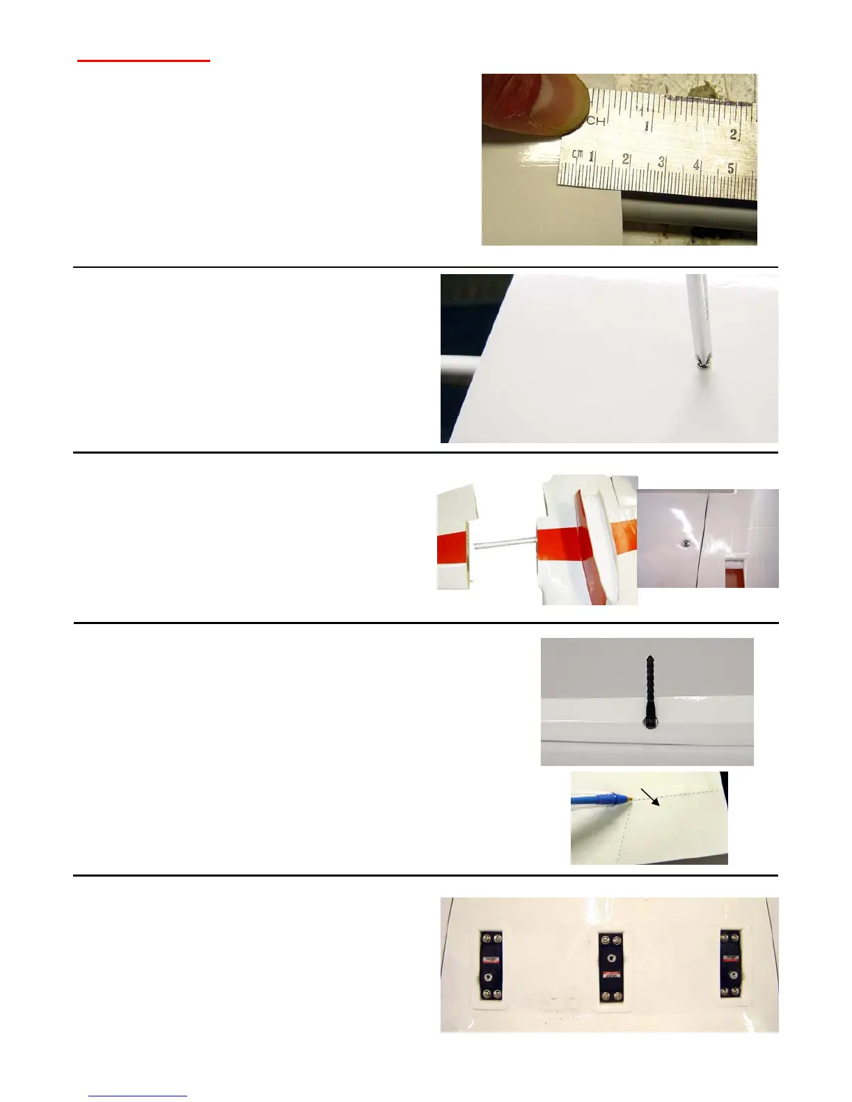
Step 5.
Three standard size servos are now mounted in the tail
area. One for each elevator half and one for the rudder.
You will also require servo extension leads
(min. 600mm length) for each of the servos.
One elevator servo will need to be reversed. With some
radio systems this can be done via the transmitter or
alternately a commercial servo reverser can be used.
Hard point.
Fuselage & Tail
Step 1.
Insert the alloy tube into a tail plane half and drill a 1.5mm
(1/16”) pilot hole through the bottom of the tail plane and the
alloy tube, 18mm inboard from the tail plane root rib.