flap
Step 26.
The flap control horn and servo is now installed the same way as
described for the aileron servo, but with one exception. Because the
flaps servos are required to move in the same direction when the
flap control is used, one servo must be reversed or the pushrods
should fitted to the same side of the servo arm on both flap servos.
Step 27.
Fit the supplied engine mounts to each nacelle. You will
need a long 3mm ball ended Allen key in order to reach
the engine mount bolts.
If using electric power, you will need to purchase four
clamp type motor mounts which fit around the motor and
then are screwed onto the supplied nylon engine mounts.
Keep the distance between the spinner back plate and
the front of the nacelle to a minimum.
If fitting glow engines, position the engine and carefully
mark and drill holes in the engine mount for the self
tapping type screws. Cut outs will need to be made for
muffler and needle valve clearance.
Step 28.
Assemble the individual tanks making sure that the
fuel line to the fuel pick up (clunk) is not to long as to
cause the ‘clunk’ to hit the rear of the tank.
For glow engine use, the fuel tanks and throttle ser-
vos are installed in each individual nacelle. The actual
position of the throttle servo is dependant on the posi-
tion of the throttle arm on the carburettor.
For electric motor use, mount the speed controller to
the back of the firewall with some double sided tape.
The electric flight battery slides in place underneath
the motor and is retained by Velcro straps (not in-
cluded). Re-useable cable ties could also be used.
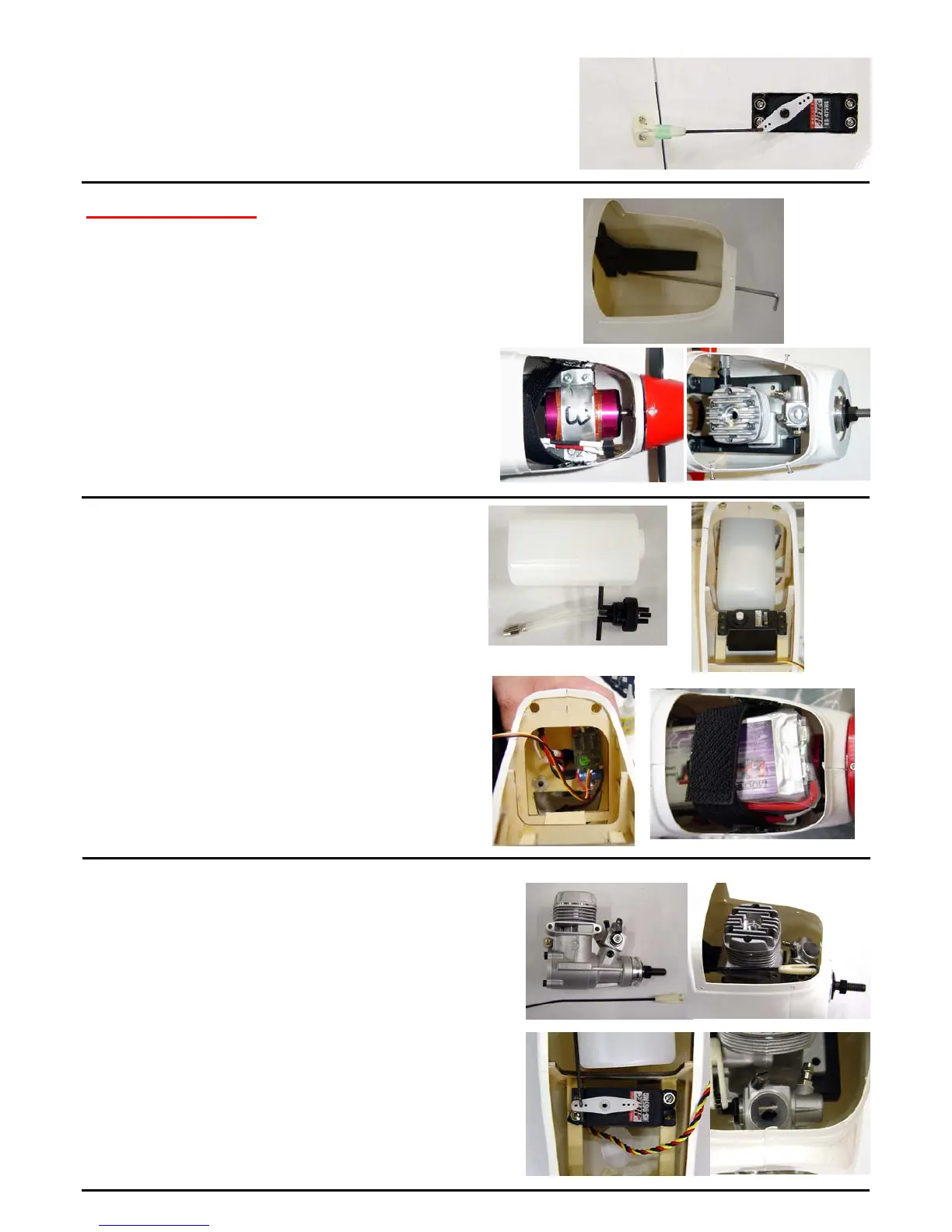
Motor Installation
Step 29.
For modellers using glow engines, take plenty of time
and make sure that all four engines are setup the same
way. This ensures that all engines will transition in a
similar way.
For two stroke engines, position the throttle arm so that it
points upwards. This gives a straighter run for the throttle
pushrod.
Connect the servo to the receiver, turn on the radio and set
the throttle stick to half throttle. Now fit the servo arm to the
servo in the position shown. Adjust the pushrod length until
the carburettor is only half open. Perform this procedure
accurately with each engine as this will give the most linear
response to the movement of the throttle stick. This is most
important with a multi engine model.