aileron
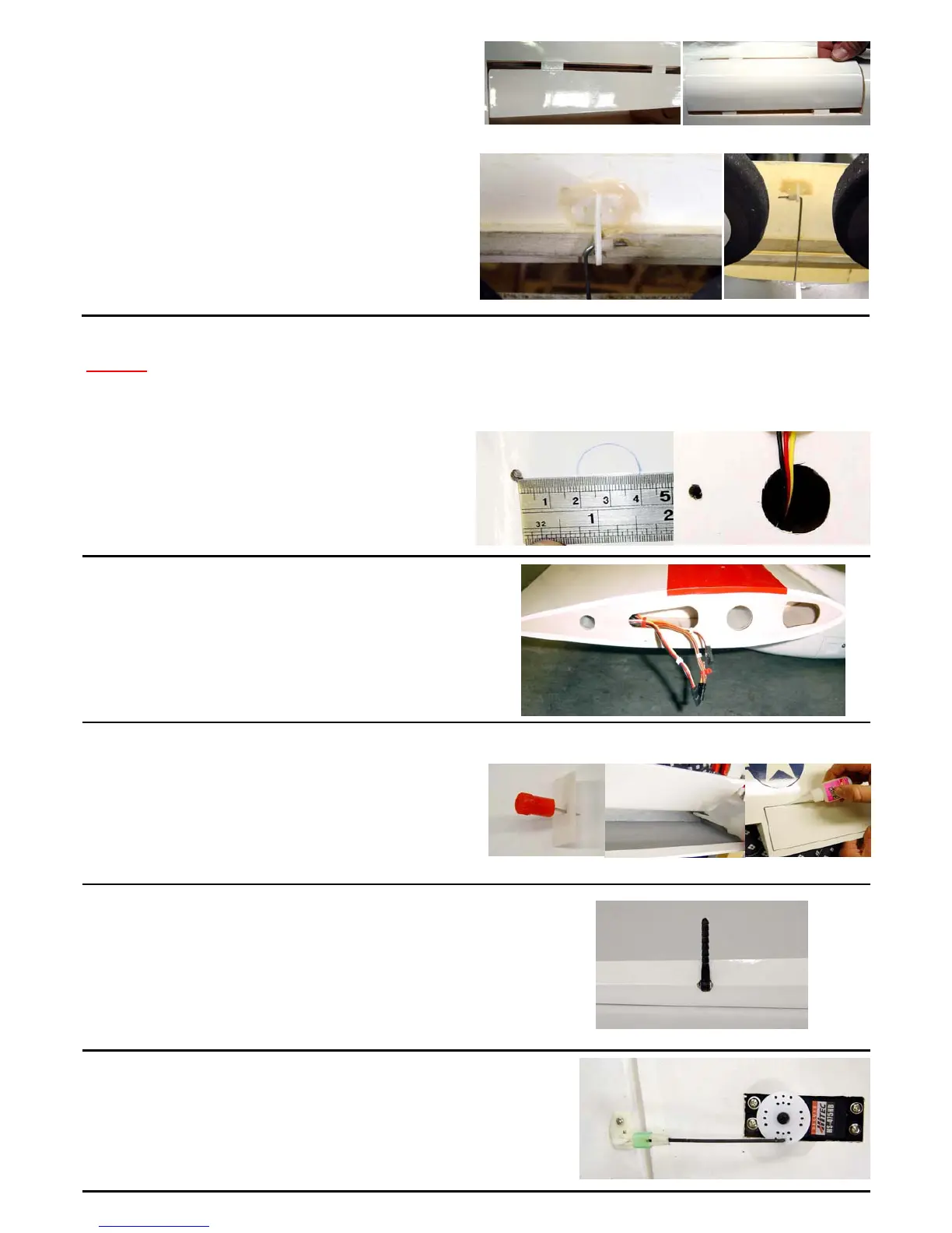
Step 25.
The aileron control horn and servo can be installed. Carefully drill a
small pilot hole in the hard point in the aileron and secure the con-
trol horn with two of the supplied screws. Locate an aileron pushrod
and fit a clevis on the end going to the control horn and make a ‘Z’
bend in the servo end of the pushrod.
Step 23.
The flaps can now be hinged using the supplied flat CA
hinges. Use a pin pushed through the middle of the
hinge to set the hinge gap and then secure with a few
drops of thin CA adhesive applied to both sides of each
hinge. Make sure the hard point installed in each con-
trol surface is facing down or underneath the aircraft.
Step 22.
Two 24” (600mm) leads will be required each wing panel.
One for the aileron and one for the outer engine nacelle.
A 6” (150mm) extension is required for the flap servo in
each wing and we recommend a 12” (300mm) extension
for the inner engine nacelles to allow for the nacelle to be
easily removed if necessary.
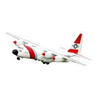
Step 21.
A number of servo extension leads need to be fed
through each wing half. To enable throttle leads to be
fed, a small access hole needs to made in the wings.
Measure 30mm from the nacelle mounting bolt
towards the leading edge and cut out a hole large
enough for the extension lead socket to fit through.
Wings
Step 24.
The ailerons are hinged using hinge point style hinges. As with the
elevators, using some light machine oil or petroleum jelly on the
hinge pivot with help prevent the epoxy from binding the hinge.
Make sure that the hinge is 90 degrees to the hinge line. Again
make sure the hard point installed in each control surface is facing
down or underneath the aircraft.
Inner gear door
Outer gear door
Step 20.
Secure the landing gear doors in place using a few
drops of thin CA adhesive applied to each hinge leav-
ing only a minimal gap between the fuselage and
gear door.
Regardless of whether fixed landing gear or the
optional retracts are to be installed, the control horns
and gear door wire should be installed.
The wire serves as a pushrod in the case of retracts
being fitted.
Inner gear door
Outer gear door