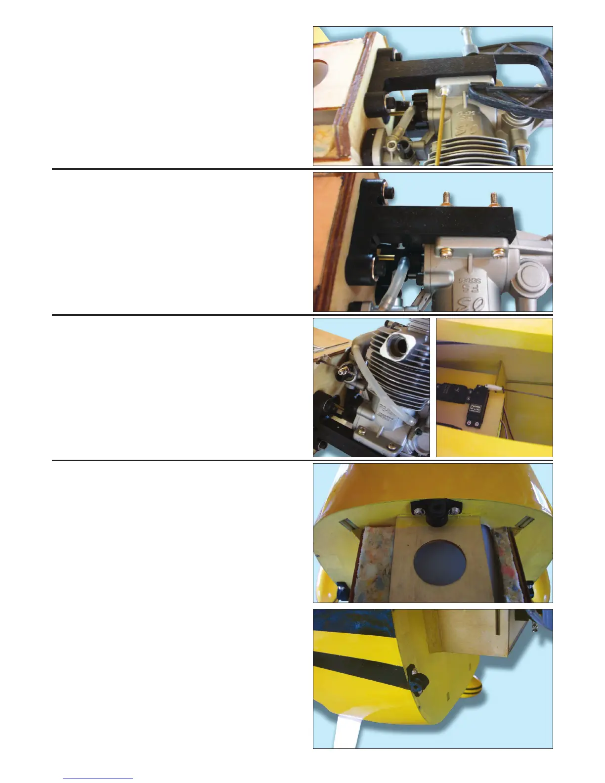
STEP 15.
Clamp your engine to the mount ensuring that the front
of the prop driver is 130mm in front of the bulkhead.
Mark the engine mount though the engine’s mounting
lugs as shown and remove the engine.
STEP 16.
Drill clearance holes in the engine mount for the
mounting bolts supplied. Connect three lengths of fuel
tubing to the tank then mount the engine.
STEP 17.
Prepare the throttle linkage by drilling a hole through the
fr
ont bulkhead as shown and fitting a pushrod
connector to the throttle arm. Mount your throttle servo
in the fr
ont of the pre-cut servo tray and use a wire
pushrod and clevis to complete.
STEP 18.
Now screw the three captive cowl retainers as shown.
Pilot drill the mounting holes first and use the self
tapping screws supplied.
_____
Page 6
_____