5
Electrode Installation
Controllers may come congured for various circulating water systems. Listed below are instructions for
cooling tower typical installations. Your specic installation requirements may dier but should conform to
these instructions as much as possible for proper operation.
Cooling Tower Installation
The standard probe(s) and/or ow assembly for cooling tower installations is constructed of schedule
80 PVC and supplied with 3/4” slip ttings for installing into a sample line. To insure proper operation
the sample line must have a ow rate of 3-10 gpm. Inlet pressure must be higher than outlet pressure in
order for water to ow past the electrode(s) to achieve the required rate. The probes are temperature
compensated for increased accuracy.
NOTES:
1. Install an isolation valve on either side of the ow assembly so electrodes can be easily
isolated for removal and cleaning.
2. A line strainer is recommended upstream from the probes to protect against fouling and
damage.
3. Systems with a ow switch require 2-3 gpm ow rate to operate outputs.
WARNINGS:
1. Electrodes are O-ring sealed, which if damaged will cause a leak.
2. Do not exceed a water temperature range of 32°F to 140°F.
3. Do not exceed a maximum pressure of 130 psi.
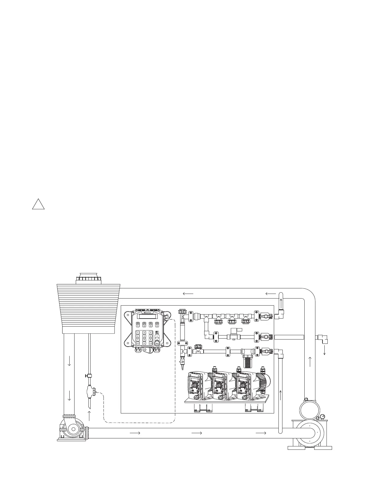
Typical Cooling Tower Installation Diagram
BLOWDOWN
COOLING TOWER
CIRCULATION
PUMP
CHILLER
MAKE-UP
WATER METER
BLEED VALVE
!