EKI-1351/EKI-1352/EKI-1521/1522/1524 User Manual 14
2.1.7 Control Mode
In controlling mode, the EKI serial device server presents a modem interface to the
attached serial device: it accepts AT-style modem commands to connect / disconnect
to other networking device. If you want serial device running application program to
connect/disconnect to different devices by request, you can use controlling mode.
The controlling mode provides three modem AT-style commands. The serial devices
can use these commands to control EKI serial device server connecting or discon-
necting to remote networking device. Thus, intelligent serial devices such as stand-
alone PLC will send /receive data to/from devices one by one via Ethernet.
2.2 Hardware
In this chapter, we will give you a overview of EKI serial device server hardware and
installation.
2.2.1 LED Indicators
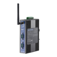
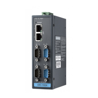
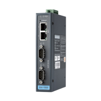
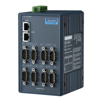
2.2.1.1 EKI-1521, EKI-1522 and EKI-1524
There are LEDs display the power status, network status, and serial communication
status located on the front panel of EKI-1521, EKI-1522, and EKI-1524, each of them
has its own specific meaning as below table.
LED Color Status Description
P1 Green ON Power input from first power connector
Off Power off
P2 Green ON Power input from second power con-
nector
Off Power off
Status Yellow Blinking System ON
Off System not work
ON Locate from Utility
LAN(Left side) Yellow ON Link
OFF No Link
Flash Active
LAN(Right side) Green ON 100M
OFF 10M
TX Yellow ON Serial port data being transmitted
OFF Serial port no data being transmitted
RX Green ON Serial port data being received
OFF Serial port no data being received