Do you have a question about the Advantech EKI-1528 and is the answer not in the manual?
Provides essential information for using the EKI-1528 and EKI-1526 serial device servers.
Details the key features and capabilities of the EKI-1528/1526, highlighting performance and connectivity.
Encompasses detailed specifications for LAN, serial, software, mechanical, power, environment, and regulatory aspects.
Lists all the items included in the EKI-1528/1526 package, including optional accessories.
Introduces the EKI-1528/1526 as a network-based serial device server for connecting RS-232/422/485 devices.
Explains the Advantech serial COM port redirector for creating virtual COM ports and accessing serial devices.
Describes the TCP server mode, supporting multiple simultaneous connections for data transfer.
Details the TCP client mode where the device server initiates connections to network hosts.
Explains serial tunneling for direct device communication over Ethernet without intermediate hosts.
Covers UDP mode for broadcasting messages and data transfer over a network.
Describes Control Mode for managing serial devices using AT-style modem commands.
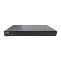
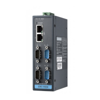
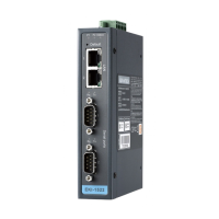
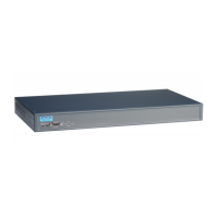
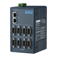
Provides an overview of the EKI-1528/1526 hardware, including panel layouts and dimensions.
Visual representation of the front and rear panel layouts for the EKI-1526 and EKI-1528.
Explains the function of various LEDs on the device for status indication.
Specifies the physical dimensions of the EKI-1528/1526 in millimeters.
Guides on connecting the EKI-1528/1526 to serial devices, power, and networks.
Illustrates the process of mounting the device into a standard equipment rack.
Details how to connect the AC power line to the device and check power indicators.
Explains how to connect serial data cables between the device and serial devices.
Guides on connecting the device to a host PC or network via Ethernet ports.
Describes connecting to the serial console port for configuration.
Provides step-by-step instructions for installing the Advantech Serial Device Server Configuration Utility.
Overview of the Advantech Serial Device Server Configuration Utility and its interface.
Explains how to discover and list serial device servers on the network using the utility.
Details the auto-search function to find device servers on the local network domain.
Guides on clearing the device list and re-searching for device servers.
Describes adding devices by IP address or range to favorites.
Guides on configuring network parameters like IP address, subnet mask, and gateway.
Details configuring serial parameters such as baud rate, parity, data bits, and stop bits.
Explains how to configure the device server's operation modes: Virtual COM, Data, and Control.
Configures the device for Virtual COM mode, allowing serial devices to act as network devices.
Details Data Mode for serial-to-network communication via TCP/UDP protocols.
Explains Control Mode for managing serial devices using AT-style modem commands.
Allows restricting access to specific IP addresses for enhanced security.
Configures email alerts and SNMP traps for various system and port events.
Sets up email alerts for events, requiring SMTP mail server settings.
Configures SNMP trap settings, including trap server IP address and community name.
Defines system events that trigger mail alerts or SNMP traps.
Configures serial port events to trigger mail alerts or SNMP traps.
Provides a tool to monitor serial ports' status, statistics, and connected IP addresses.
Offers administrator settings for easy management, including import/export and locking.
Allows importing or exporting device settings via .conf files.
Imports or exports serial port settings using .sps files.
Helps identify a specific device server by activating its status LED and buzzer.
Enables password protection for the device server to enhance security.
Restores the serial device server to its original factory default settings.
Guides on updating the device server's firmware for the latest features.
Details how to use COM port mapping software to create and manage virtual COM ports.
Guides on automatically mapping serial ports to virtual COM ports using the utility.
Explains how to manually map specific serial ports to virtual COM ports on the host.
Describes direct mapping of virtual COM ports without physical connection.
Details methods for removing individual or groups of mapped virtual COM ports.
Explains how to perform diagnostic tests on serial ports and communication parameters.
Introduces configuring the EKI-1500 serial device server via a web interface.
Details how to access the device server's web interface using a web browser.
Allows changing device name, description, enabling/disabling functions, and setting timezone.
Configures network parameters like IP address, subnet mask, gateway, and DNS via web interface.
Details basic, operation mode, and advanced settings for serial port configuration via web.
Enables monitoring of serial ports settings, statistics, and connected IP addresses via web.
Configures email server and SNMP Trap server for auto warning alerts via web.
Allows changing the serial device server's login password via web interface.
Enables importing or exporting device settings via .conf files through web interface.
Initiates a device reboot via web interface to apply configurations.
Provides an overview of console configuration for managing the device and changing passwords.
Guides on creating a Telnet connection for console configuration, including IP and port details.
Explains connecting to the serial console port for configuration using terminal software.
Lists available console commands for system management and configuration.
Details the pin assignments for the RS-232 serial port connector.
Provides pin assignment details for RJ-45 cables used with RS-422 and RS-485 interfaces.
| Serial Standards | RS-232/422/485 |
|---|---|
| Operating Temperature | -10°C to 60°C (14°F to 140°F) |
| Power Input | 12 to 48 VDC, 24 VAC |
| Ethernet | 10/100Base-T(X) |
| Protocols | DHCP, HTTP, SNMP, SMTP, Telnet, Modbus/TCP |
| Mounting | DIN-rail, Wall |
| Certifications | CE, FCC, UL |