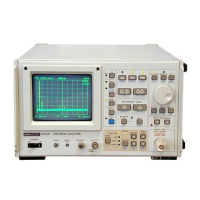
The Advantest R4131 Series is a spectrum analyzer designed for a wide range of measurement and analysis tasks. This instruction manual covers various models within the R4131 series, including R4131A, R4131AN, R4131B, R4131BN, R4131C, R4131CN, R4131D, and R4131DN.
Function Description:
The R4131 Series spectrum analyzer is equipped with a comprehensive set of functions for signal analysis. Its core operation involves converting input RF signals into intermediate frequency (IF) signals, processing them, and displaying the resulting waveform on a CRT screen.
Key functional blocks include:
- RF Input and Attenuation: The device accepts RF input signals, which first pass through a 50 dB RF input attenuator.
- Mixers: The signal then enters a series of mixers (first, second, third, and fourth) that down-convert the frequency. The first mixer mixes the input signal with a local signal from a 4 to 7.5 GHz YTO (YIG tuning transmitter) to produce a 4 GHz first IF signal. Subsequent mixers further reduce the IF to 226 MHz, 26.4 MHz, and finally 3.58 MHz.
- YTO Control: The YTO circuit controls the sweep range from 4 to 7.5 GHz and adjusts the center frequency with a maximum resolution of 500 Hz.
- IF Filters: The 3.58 MHz IF signal passes through LC and crystal filters, which select the resolution bandwidth from 1 MHz down to 1 kHz. The output level is controlled by a STEP AMP with 0.25 dB resolution over a 50 dB range.
- Logarithmic Amplifier (LOG AMP): The IF signal enters a LOG AMP with an 80 dB dynamic range, where it undergoes logarithmic compression before detection and conversion to a DC output.
- Video Filter: The detected signal then passes through a video filter, which selects the video filter bandwidth from 1 MHz down to 10 Hz, producing the Y.OUT signal.
- A/D Conversion and Display: Both the Y.OUT (ordinates axis) and X.OUT (quadrature axis, from the RAMP signal) are converted from analog to digital signals at 9 bits (512 points) and 10 bits (1024 points), respectively. These digital signals are stored in memory and controlled by the CPU for waveform display on the CRT.
- Memory Functions: The R4131 features two main memories: a WRITE memory that rewrites data with each sweep, and a VIEW memory that stores the displayed waveform. It also includes a non-volatile memory for data retention even after power-off.
- Signal Processing: The device performs MAX HOLD and normalization processing using the WRITE and VIEW memories, along with the CPU's arithmetic operation function.
- Automatic Frequency Control (AFC): Models R4131B/BN/D/DN include an AFC block that operates at frequency spans of 200 MHz or smaller, applying AFC to the YTO within a band from 4 to 6.5 GHz to improve center frequency setting accuracy.
Important Technical Specifications:
- Frequency Range: 10 kHz to 3.5 GHz.
- Frequency Display: Displayed on the CRT screen with a maximum resolution of 1 kHz (adjustable based on frequency span).
- Frequency Displaying Accuracy (after ZERO CAL):
- R4131A/AN/C/CN: Less than ±10 MHz.
- R4131B/BN/D/DN: ±100 kHz + SPAN 3% or less (within 0 Hz to 2.5 GHz center frequency and 5 ms to 0.5 S/DIV sweep time).
- All models: ±10 MHz (center frequency 2 GHz or more).
- Frequency Span: 4 GHz to 100 kHz, with 1-2-5 step selection. ZERO span mode is available.
- Frequency Span Accuracy: ±5%.
- Frequency Stability (after 30 min. power ON):
- R4131A/AN/C/CN: Less than 100 kHz/5 min.
- R4131B/BN/D/DN: Less than 10 kHz/5 min (within 0 Hz to 2.5 GHz center frequency and 5 ms to 0.5 S/DIV sweep time).
- Residual FM: Less than 2 kHzp-p/100 ms.
- Noise Sideband: More than 80 dBc (with 1 kHz RBW, 10 Hz video filter, 20 kHz detuned from signal).
- Amplitude Display Range: LOG 80 dB (10 dB/DIV), 20 dB (2 dB/DIV), 40 dB (5 dB/DIV, QP mode only), LIN 10 DIV.
- Linearity: LOG ±0.15 dB/1 dB, ±1 dB/10 dB, ±1.5 dB/70 dB or more. Less than 5% of LIN scale.
- Reference Level: LOG -69 dBm to +40 dBm (R4131A/B/C/D), 40.25 dBµ to 150 dBµ (R4131AN/BN/CN/DN). Steps of 10 dB, 1 dB, 0.25 dB.
- Reference Level Accuracy: Less than ±1 dB in LOG mode (after calibration at 200 MHz, 10 dB ATT, 0 to 59 dBm input for R4131A/B/C/D, and 110 dBµ to 51 dBµ for R4131AN/BN/CN/DN).
- Sweep Time: 5 ms/div to 100 s/div, with 1-2-5 step.
- Sweep Time Accuracy: Less than ±15%.
- Sweep Trigger: FREE RUN, LINE, VIDEO, and SINGLE (Reset/Start).
- RF Input Connector: Approx. 50 Ω N-type (R4131A/B/C/D), Approx. 75 Ω N-type (R4131AN/BN/CN/DN).
- Maximum Input Level: +20 dBm, ±25 VDCmax (127 dBµ, ±25 VDCmax).
- Input ATT: 0 to 50 dB.
- Input ATT Selecting Accuracy: ±1 dB or less (±1.5 dB or less).
- Input VSWR:
- R4131A/B/C/D: 1.5 or less (100 kHz to 2 GHz), 2.0 or less (2 GHz to 3.5 GHz).
- R4131AN/BN/CN/DN: 1.5 or less (100 kHz to 1.5 GHz), 2.0 or less (10 kHz to 2 GHz), 2.5 or less (2 GHz to 3.5 GHz).
- GPIB Interface: Conforms to IEEE Standards 488-1978, enabling full remote control.
Usage Features:
- Intuitive Operation: The manual provides a basic operating procedure covering initialization, signal input, setting center frequency, frequency span, reference level, and marker usage.
- GPIB Programming: The device supports GPIB for remote control, allowing users to program settings and retrieve data. Examples are provided for setting various parameters like center frequency, frequency span, reference level, and marker frequency using GPIB commands.
- Trace Data Input/Output: Trace data (waveform displayed on screen) can be input or output in ASCII or binary code, facilitating external analysis and processing.
- Mode String Output: The device can output a "mode string" containing the setting status of various functions (e.g., input attenuator, reference level unit, trigger mode, data knob setting, AFC mode).
- Status Byte: The GPIB service request function allows detection of various statuses, such as end of sweep, calibration completion, signal track completion, and marker search completion.
Maintenance Features:
- Calibration and Adjustments: The manual details procedures for basic checks and calibration, including A/D adjustment, LOG amplifier adjustment, IF filter adjustment (BPF, crystal, LC, step amplifier), and YTO-CONT adjustment.
- Performance Testing: Comprehensive performance tests are outlined for frequency span accuracy, center frequency readout accuracy, residual FM, noise sidebands, resolution bandwidth accuracy and selectivity, LOG/LIN linearity, reference level accuracy, gain compression, frequency response, average noise level, sweep time accuracy, and calibrated output accuracy.
- Storage and Shipment: Guidelines are provided for proper storage conditions (temperature, covering) and cleaning (CRT display filter). For shipment, using original packing materials or equivalent shock-absorbing materials is recommended.
- Self-Test: The R4131 performs a self-test for RAM and ROM on the CPU board upon power-on, displaying error messages if failures are detected.
- Accessories: The manual lists various accessories such as RF couplers (TR1625, TR1626), antennas (TR1711 Log-periodic, TR1722 Half-wave Dipole, TR1720 Loop, TR17201 Active, TR17203 Active Dipole, TR17204 Log-periodic, TR17205 Log-spiral, TR17206 Double-ridged Guide), filters (MEP-292 to MEP-295, TR14101, TR14201 to TR14204), a BNCP-FJ Conversion Adaptor, an earphone for voice monitor, and various connection cables (BNC-BNC, BNC-SMA, GPIB).