6 Installation
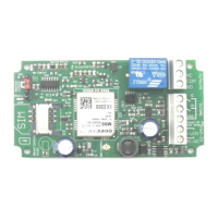
6.1 Power Connection
A fused AC or DC power supply of between 12 and 24V (MAX!) should be used with this
unit. AC voltages over 27VAC will cause the on board thermal fuse to trip and may cause
erratic operation. We recommend you measure the supply voltage when using AC to en-
sure it does not exceed this voltage during normal operation.
AC power supplies should be connected to either of the ~VIN terminals. Similarly DC sup-
plies should be connected to these terminals with the polarity connected either way
around (i.e. +ve and –ve connected to either of the ~VIN terminals).
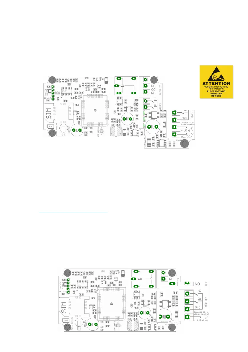
If DC supply voltages are liable to drop below 12VDC or it is mandatory that the GND termi-
nal be at the same voltage level as the supply ground, connect the negative (0v) supply to
the GND terminal and the supply +ve to the outer-most ~VIN terminal (terminal number 5).
This will bypass the bridge rectifier for the GND negative supply.
Please note if using this equipment in a motor vehicle please consult Advent Controls prior
to fitting (support@adventcontrols.co.uk)
6.2 Input Connection
The inputs are optically isolated from the digital circuitry. Both inputs are active low and
should be connected to the GND terminal in the active state. Input impedance is 4.4kΩ
and is limited to 13V max. The input features protection against over-voltage but should
not exceed 50V.