16
INSTALLATION
9. Installation
9.1 Appliance installation
» Mark out the holes for drilling using the installation
template supplied.
» Drill the holes and insert suitable rawl plugs.
» Secure the wall mounting bracket using suitable
screws.
» Hang the appliance on the wall mounting bracket.
9.2 Water connection
!
Material losses
Carry out all water connection and installation work
in accordance with regulations.
!
Material losses
The appliance may develop a leak and cease func-
tioning.
» Never subject the appliance to water pressure.
» Never interchange the water connections.
» Set the ow rate (see tap instructions). Note the
maximum permissible ow rate of 5 l/min when
the tap is fully opened to the "hot" position.
!
Material losses
When tightening the ttings, counterhold with a suit-
able spanner.
22
19
D0000064698
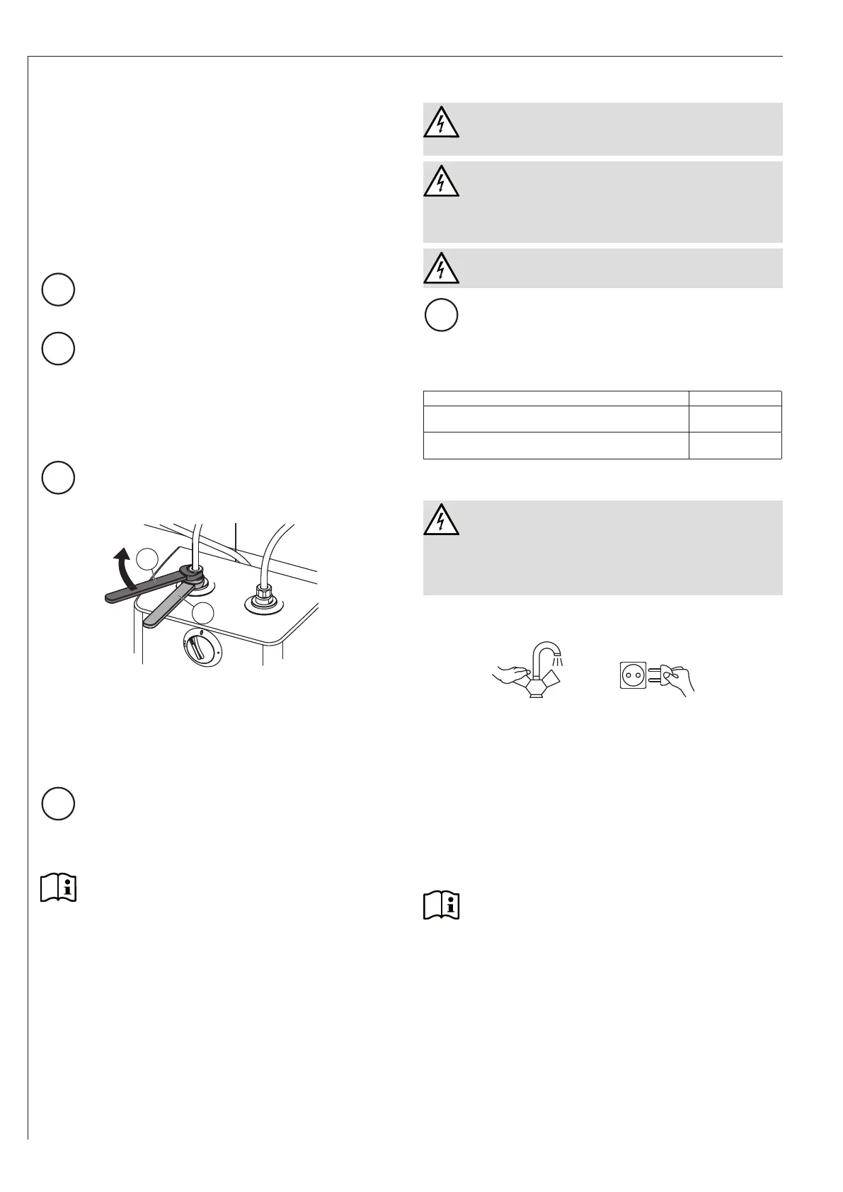
Match up the colour coding on the tap water connections
and the appliance:
◦ R.h. side blue = "Cold water inlet"
◦ L.h. side red = "DHW outlet"
» Secure the water connections from the tap to the
appliance.
!
Material losses
Fixed water lines are not permitted between the ap-
pliance and the tap.
Never t hose extensions, aerators or water savers
to the tap outlet.
Note
Ensure that the water connections are not kinked
during installation. Prevent any tensioning during
installation.
9.3 Power supply
WARNING Electrocution
Carry out all electrical connection and installation
work in accordance with relevant regulations.
WARNING Electrocution
In the case of a permanent connection, the appliance
must be able to be separated from the power supply
by an isolator that disconnects all poles with at least
3 mm contact separation.
WARNING Electrocution
Ensure that the appliance is earthed.
!
Material losses
The voltage specied on the type plate must match
the mains voltage.
» Observe the type plate.
The following electrical connections are permissible:
U5
Connection to a freely accessible standard socket
with matching plug
X
Permanent connection to an appliance junction box
with earth conductor
X
10. Commissioning
WARNING Electrocution
◦ Commissioning may only be carried out by a
qualied contractor in accordance with safety
regulations.
◦ The appliance must be completely lled with
water prior to commissioning.
10.1 Initial start-up
1. 2.
D0000049325
» Either open the DHW valve of the tap or set the
mono lever mixer tap to "hot" for at least 60 seconds
until the water that ows out is free of air bubbles.
» Check the entire hydraulic installation for tightness.
» Turn the temperature selector to the maximum
temperature.
» Insert the plug into the standard socket or set the
fuse/MCB in the distribution board.
» Check the function of the appliance using the heat-
up indicator. Ensure that the temperature controller
switches off.
Note
If you fail to follow the correct sequence (rst water,
then power), the high limit safety cut-out will trip.
Proceed as follows:
» Disconnect the appliance from the power sup-
ply.
» Fill the appliance with water.
» Connect the appliance to the power supply.