17
INSTALLATION
10.1.1 Appliance handover
» Explain the functions of the appliance to the user.
Show the user how to operate the appliance.
» Make the user aware of potential dangers, especially
the risk of scalding.
» Hand over these instructions and, if applicable, the
instructions for any accessories.
10.2 Recommissioning
See chapter "Installation / Commissioning / Initial start-
up".
11. Shutdown
» Isolate the appliance from the power supply by
removing the plug or by tripping the MCB in the
distribution board.
» Shut off the domestic water supply via the angle
valve.
» Disconnect the water connections from the appliance
tap.
» Drain the appliance (see chapter "Installation / Main-
tenance / Draining the appliance").
12. Troubleshooting
Fault Cause Remedy
The appli-
ance does
not supply
hot water.
The high limit safety
cut-out has tripped.
Remedy the cause of the fault.
Allow the appliance to cool
down. If you have isolated the
appliance from the power sup-
ply, the high limit safety cut-out
will be reset automatically.
The appliance is not
completely filled with
water.
Fill the appliance (see chapter
"Commissioning / Initial start-
up").
The tap has not been
connected correctly.
Connect the tap correctly (see
chapter "Installation / Water
connection")
Water contin-
ues to run on
for too long
after closing
the tap
Excessive pressure
or flow rate
Reduce the flow rate at the tap.
13. Maintenance
WARNING Electrocution
Before any work on the appliance, disconnect all
poles of the appliance from the power supply.
» Dismantle the appliance for maintenance work.
13.1 Draining the appliance
WARNING Burns
Hot water may escape during draining.
» Take the appliance out of use (see chapter "Installa-
tion / Shutdown").
» Lift the appliance off its wall mounting bracket.
» Drain the appliance via its connectors.
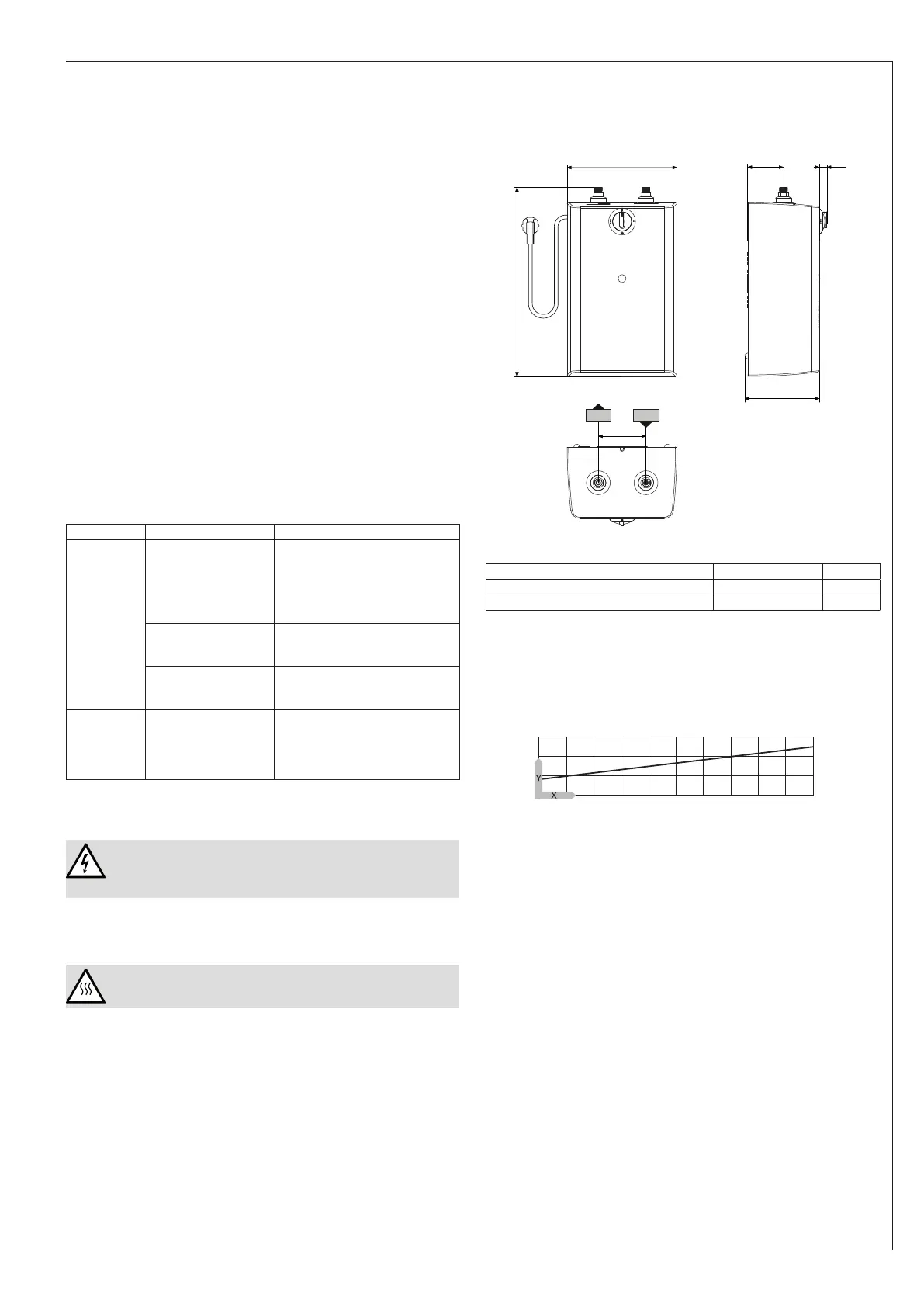
14. Specication
14.1 Dimensions and connections
230
365
75 15
155
c06
c01
100
D0000064696
U5
c01 Cold water inlet Male thread G 3/8 A
c06 DHW outlet Male thread G 3/8 A
14.2 Heat-up diagram
The heat-up period depends on the degree of scaling
and residual heat. For the heat-up time for a cold water
supply at 10 °C and a maximum temperature setting, see
the diagram.
35 40 45 50 55 60 65 70 75 80 85
0
5
10
15
D0000047175
x Temperature in °C
y Duration in min
14.3 Country-specic approvals and
certications
See the type plate for test symbols.
14.4 Extreme operating and fault conditions
In the case of faults, a peak temperature of up to 100 °C
may briey occur in the system.