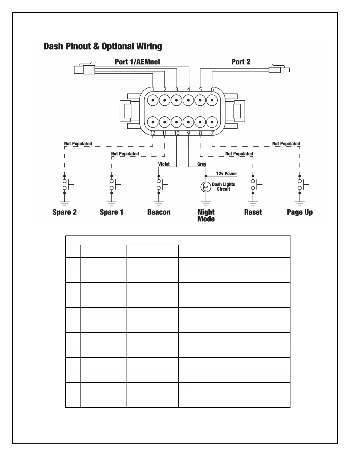
5
Figure 4 - Connector Interfaces
Connect to switched, fused +12v power source
Ensure good ground connection that isn't shared with high
noise emitters such as ignition systems
CAN+; ty pically reserv ed f or AEMnet dev ices; use twisted
pair wiring to minimize signal noise
CAN-; typically reserved for AEMnet devices; use twisted
pair wiring to minimize signal noise
CAN+; f or use with third party CAN dev ices; use twisted pair
wiring to minimize signal noise
CAN-; for use with third party CAN devices; use twisted pair
wiring to minimize signal noise
*OPTIONAL* Remote Page Up (left dash button) input; use
momentary switch to ground
*OPTIONAL* Remote Reset (right dash button) input; use
momentary switch to ground
*OPTIONAL* Triggers Night Mode to dim dash display;
connect to 12v dash lights circuit
*OPTIONAL* Sets start/f inish line beacon if using GPS f or
track mapping; use momentary switch to ground
*OPTIONAL* Spare switch input; typically used f or turn
signals; switch must connect to ground
*OPTIONAL* Spare switch input; typically used f or turn
signals; switch must connect to ground

 Loading...