MODEL 5600 REPAIR & CALIBRATION MANUAL CAT# 1431.01
10
REVISION 7: June 11, 1999
FILE LOCATION: E.F. Disk - Manuals - Cal. Man. - Model 5600.DOC
10/27/99
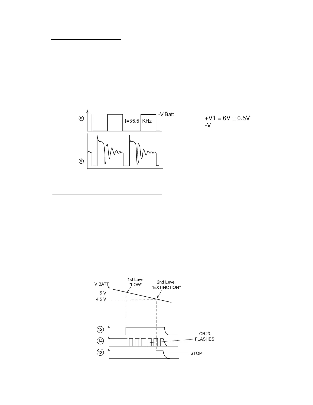
b) OSCILLATOR – SUPPLY
Oscillator is composed of Z8; R43; R44; C11
At point (8) there is a square wave frequency = 35 kHz which is supplied to Q6
and Q7, Q8 Darlington Amp Circuit causing transformer T1 to ring at its input.
Regulation is made by circuit Z9A, its inputs are connected on one side to
reference 2.5V (CR22 : LM336Z) and on the other side to bridge R49, R50 image
of voltage V2.
Supply Voltages:
c) LOW AND EXTINCTION DETECTIONS
Link R54; R55; R57 is calculated so as to get:
a) 2.5V on (11) when battery is on 5V
b) 2.5V on (10) when battery is on 4.5V
Case a): Voltage goes under 5V then Z9b changes to Vsat+. Oscillator Z6; C19;
R61 starts and triggers Q9 that makes LED CR23 flash.
Case b): Voltage goes under 4.5V then Z9C changes to Vsat+ and triggers
instrument extinction through CR11 acting directly on Q3. This stops the
instrument without Z5. To start the instrument press S1 twice (first pressing will
set back Z5 properly).
8
9
-V Batt
f=35.5 KHz
+V1 = 6V ± 0.5V
-V1 = 6V ± 0.5V
+V2 = 18.5V ± 0.8
13
14
12
VBATT
5V
4.5 V
1st Level
"LOW"
2nd Level
"EXTINCTION"
CR23
FLASHES
STOP

 Loading...


