MODEL 5600 REPAIR & CALIBRATION MANUAL CAT# 1431.01
11
REVISION 7: June 11, 1999
FILE LOCATION: E.F. Disk - Manuals - Cal. Man. - Model 5600.DOC
10/27/99
d) FAULT AND AUTOMATIC STOP
Detection is made at terminals C1 and C2.
When current circuit is not closed by a resistance to measure, then C1 is on
potential +Batt and C2 on potential –Batt.
As for measurement, there can be up to 2V between C1 and C2 on range 200
Ω
x 10 mA.
Whether level is >2V (R23; R24) there is no measurement, or at least a
resistance >> to range.
At point (15) there is VC1 C2 (rectification is necessary since measurement is
also possible in (-) and VC1 C2 can be positive or negative).
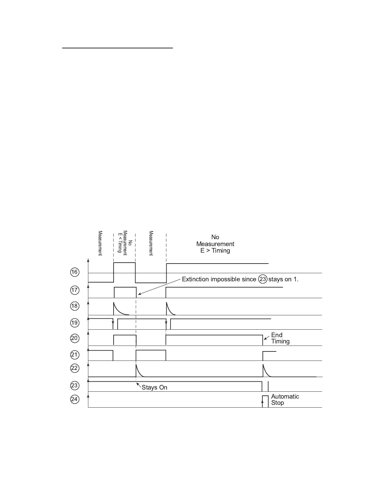
When opening circuit C1, C2, voltage at point (15) now becomes superior to R23
level; R24 and (16) change to +Vsat.
Diode CR17 lights on.
Signal (16) will trigger extinction timing control. Z4 is a 555 timer set in
monostable way its timing control is given by formula: t = -(R32 C5 x Ln 1/3) =
241s. (4mn) and triggers on falling edge of Trigger (2) input.
If a measurement is made before end of timing control (17) falls down to 0 and
modifies extinction forcing a level 1 on (23). On the contrary, timing control goes
normally and once finished it triggers extinction of the instrument.
Stays On
Automatic
Stop
End
Timing
Measurement
Measurement
No
Measurement
E < Timing
No
Measurement
E > Timing
Extinction impossible since stays on 1.
16
17
18
19
20
21
22
23
24
23

 Loading...


