Innovation Water Heaters Installation, Operation & Maintenance Manual
CHAPTER 5 – SAFETY DEVICE TESTING
Page 68 of 206 AERCO International, Inc. • 100 Oritani Dr. • Blauvelt, NY 10913 OMM-0078_0L
PRI: 11/25/2014 Phone: 800-526-0288 GF-128
Low Gas Pressure Fault Test – Continued
9. Upon test completion, close the ball valve and remove the manometer. Replace the 1/8“
plug removed in step 1.
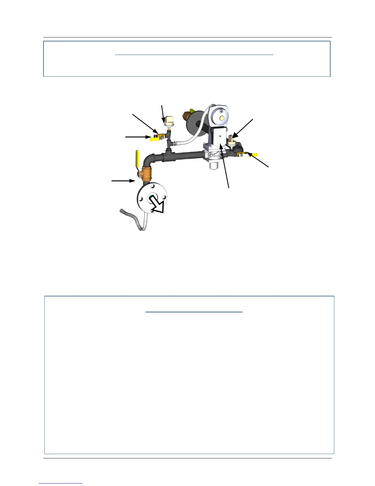
Figure 5-1. Low & High Gas Pressure Testing (INN600-1060 Gas Train)
5.3 HIGH GAS PRESSURE FAULT TEST
To simulate a high gas pressure fault, refer to Figure 5-1 and proceed as follows:
High Gas Pressure Fault
1. Remove the 1/8“ plug from the leak detection ball valve shown in Figure 5-1.
2. Install a 0 – 16” W.C. manometer (or W.C. gauge) where the 1/8” plug was removed.
3. Slowly open the leak detection ball valve
4. Start the unit in Manual mode at a valve position (firing rate) of 25%.
5. Slowly increase the gas pressure using the adjustment screw on the SSOV.
6. The unit should shut down and display a HIGH GAS PRESSURE fault message when the
gas pressure exceeds 4.0” W.C. The FAULT indicator should also start flashing.
7. Reduce the gas pressure back to 2.8” W.C.
8. Press the CLEAR button on the Control Box to clear the fault.
9. The fault message should clear and the FAULT indicator should go off. The unit should
restart.
10. Upon test completion, close the ball valve and remove the manometer. Replace the 1/8“
plug removed in step 1.
SHUTOFF
VALVE
1/4" NPT PLUG
(Install manometer here for
HIGH gas pressure test)
LEAK DETECTION
BALL VALVE
TO AIR/FUEL VALVE
LOW GAS
PRESSURE SWITCH
1/4" NPT PLUG
(Install manometer here for
LOW gas pressure test)
 Loading...