Do you have a question about the AERMEC 1402 and is the answer not in the manual?
Instructions for preserving manual and ensuring accessibility for maintenance.
Safety measures and installation requirements for qualified personnel.
Details on "Cooling Only" versions and their operating limits.
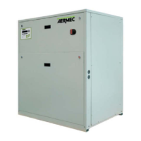
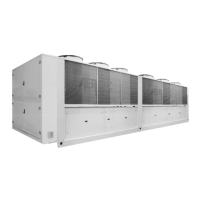
Overview of available NS series sizes and configuration options.
Detailed description of chiller circuit components like compressors and heat exchangers.
Description of the unit's frame and fan assembly, including protection.
Explanation of safety and control components like pressure switches and transducers.
Description of electrical components like the panel, disconnecting switch, and control keypad.
Details on microprocessor functions, display, and user operations.
Description of accessories for electric regulation like AER485P1 and AERWEB30.
Details on electrical accessories like RIFNS and DCPX.
Description of general accessories like GP, AK, and AVX.
Technical data including cooling capacity, power, and electrical specifications for specific models.
Technical specifications for models NS 2002 to 3402, covering various performance parameters.
Technical data for NS models 3602 to 5702, including sound levels and dimensions.
Technical data for NS models 6003 to 7203, covering cooling capacity, power, and electrical parameters.
Graphs showing operating limits for versions '°' and 'L' based on temperatures.
Operating limits for specific models 5402-5702, versions 'A' and 'E'.
Design data including maximum allowable pressure and temperature limits.
Operating limits for versions 'A' and 'E' across different models.
Correction factors for standard version units based on air and water temperatures.
Correction factors for standard silenced versions, considering air and water temperatures.
Correction factors for silenced high efficiency versions, considering temperature variations.
Correction factors for silenced high efficiency versions, considering temperature variations.
Fouling factors and correction coefficients for heat exchanger cleanliness.
Guide on interpreting graphs to determine glycol percentage and correction factors.
Recommended minimum water content for different unit sizes and compressor counts.
Pressure drop curves for desuperheaters based on water flow rate.
Pressure drop curves for total recovery units based on water flow rate.
Corrective factors for total recovery water temperatures different from nominal.
Information on pump selection based on model and water flow rate.
Sound levels for standard NS units under full load, broken down by octave bands.
Sound levels for silenced NS units under full load, octave band data.
Sound levels for silenced high efficiency NS units, octave band data.
Settings for safety and check parameters like cold setting and antifreeze intervention.
Calibration values for fan thermomagnetic switches (MTV1, MTV2, MTV3).
Calibration values for compressor thermomagnetic switches (MTC1, MTC2, MTC3).
Calibration values for compressor thermal relays (RT1, RT2, RT3).
Fuse ratings for compressors (F1, F2, F3).
Specifications for high/low pressure switches and transducers.
Safety valve pressure ratings for cooling circuits.
Guidelines for positioning the unit, considering weight and access.
Minimum required spaces around the unit for installation and maintenance.
Dimensional tables and weight distribution for units with 3780mm carpentry.
Water connection diagrams for NS 1402-1602-1802 models, versions °/L.
Water connection diagrams for NS 1601 model, versions A/E.
Dimensional tables for units with 4770mm carpentry, models 2101-2401.
Dimensional tables for units with 4770mm carpentry, model 1801.
Dimensional tables for units with 4770mm carpentry, models 2002-2502.
Dimensional tables for units with 4770mm carpentry, model 1802.
Water connection diagrams for NS 2101 model, versions °/L.
Water connection diagrams for NS 2202-2352-2502 models, versions °/L.
Dimensional tables for units with 5750mm carpentry, models 2652-2802.
Dimensional tables for units with 5750mm carpentry, models 2101-2802.
Water connection diagrams for NS 3002 model, versions A/E.
Water connection diagrams for NS 3202 model, versions A/E.
Dimensional tables for units with 7160mm carpentry, models 3402-3602.
Water connection diagrams for NS 3002 model, versions A/E.
Water connection diagrams for NS 3202 model, versions A/E.
Dimensional tables for units with 7160mm carpentry, models 3402-3602.
Dimensional tables for units with 8150mm carpentry, models 3902-4202.
Dimensional tables for units with 8150mm carpentry, model 3402.
Water connection diagrams for NS 3402 model, versions A/E.
Dimensional tables for units with 9140mm carpentry, models 4502-4802.
Dimensional tables for units with 9140mm carpentry, model 3602.
Water connection diagrams for NS 4802 model, versions °/L.
Water connection diagrams for NS 3602 model, versions A/E.
Dimensional tables for units with 10120mm carpentry, models 3902-4202.
Dimensional tables for units with 11100mm carpentry, model 5702.
Dimensional tables for units with 11100mm carpentry, models 4502-4802.
Dimensional tables for units with 11100mm carpentry, models 5002-5702.
Water connection diagrams for NS 5702 model, versions °/L.
Water connection diagrams for NS 5002 model, versions A/E.
Dimensional tables for units with 10120mm carpentry, model 5002.
Dimensional tables for units with 11100mm carpentry, model 5202.
Dimensional tables for units with 10120mm carpentry, model 5402.
Dimensional tables for units with 12520mm carpentry, models 6303-6603.
Water connection diagrams for NS 6603 model, versions °/L.
Dimensional tables for units with 13510mm carpentry, models 6903-7203.
Water connection diagrams for NS 7203 model, versions °/L.
Recommendations for external hydraulic circuit installation and components.
Procedure for loading the water system, including pressure checks.
Procedure for safely emptying the water system, including disposal warnings.
Recommended electric cable sections based on length and unit power.
Instructions for connecting to the power supply, including panel access.
How to connect the unit's power supply and network cables.
Steps for preparing the unit before commissioning, safety checks.
Procedure for the initial startup of the machine after installation.
Checks required for seasonal changeover, including electrical and noise checks.
Default cooling set point and temperature difference (Δt).
Functions to prevent compressor start-up too close to each other.
How the electronic board manages the circulation pump and flow rate alarm.
Functionality of the anti-freeze alarm and warnings for intervention.
Water flow rate alarm function and its effect on compressor and pump.
Controls for the hydraulic circuit, including filling, filters, and pressure.
Controls for the electric circuit, including safety devices and connections.
Controls for the chiller circuit, including compressors, pressure, and filter-drier.
Checks for tightening of panels, compressors, and structure condition.