25
A
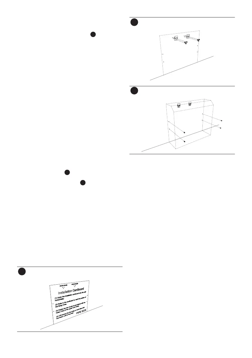
1. Choose the mounting position on the wall.
2. Find the points where drill the wall using as a
reference the cardboard template supplied. Mark
the wall and remove the template (
A
).
3. Choose the screw anchors as a function of the type
of wall and of the load which will have to withstand.
4. Run on the wall holes to proper diameter dowels to
be used.
The unit provides input connections in 4 directions:
• Rear left, the connections have to pass through the
wall, it requires a service hole on the wall.
• Left (remove the push on the left side of the unit and
the side edge), the connections must be protected
with a cable duct in views.
• Rear right, the connections have to cross the wall
and requires a service hole on the wall.
• Right (remove the push on the right side of the
unit and the side edge), the connections must be
protected with a cable duct in views.
• Service hole (if the installation requires it), diameter
55-65mm (for power supply line and communication
with the external unit, condensate and copper
tubes), made according to the type of installation
required and based on distances specified in the
schemes at the bottom.
5. The hole should have a slight outward slope.
6. Place a pipe sleeve in the hole to protect the service
lines that you have to scroll through.
7. Fix the wall brackets (
B
).
8. Hook the indoor unit to the supports and secure it
with 4 screws and wall plugs (
C
)
9. Make all connections, from the point where they
must be connected to the indoor unit to the
outdoor unit through the service hole.
10. Seal the service hole with material appropriate to
the type of wall.
11. Make all connections as shown in the chapters (on
the manual of outdoor unit).
12. Make sure that the air filters are in position.
B
C