25
INSTALLAZIONE
•
INSTALLATION
The units must be installed on a perfectly horizontal floor,
and minimum technical spaces must be left around them to
ensure the free circulation of air and maintenance opera-
tion.
To select and install any antivibration materials see dimen-
sions, weights and barycenter.
WATER CONNECTIONS
The position of water inlet and outlet of heat pump models
are inverted in respect of cooling only models and are
shown in the units.
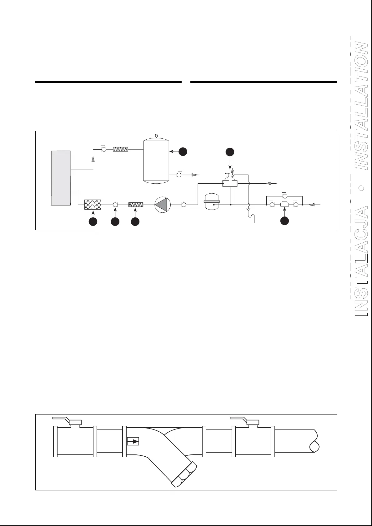
Following accessories should be installed in the system (see
figure below):
– water tank to reduce the compressor starts (1);
– high pressure flexible joints to avoid transmission of vibra-
tions to water pipings (2);
– hand gate valves between the unit and the system to
allow maintenance without empting the water of the
whole system (3);
– air bleed with safety valve (4);
– automatic water refill with pressure gauge (5);
Water filter supplied with the unit must be installed (point
6 of previous figure). Water filter is packed up together
with the unit, but not already mounted on it.
For filter installation see the belowe figure.
The units are also standard supplied with a kit to be installed
by the water connections to drain the water off the circuit.
During operation of the heat pump models, the water pro-
duced during the defrosting cycle is removed through the
bottom side of the unit.
2
3
4
5
1
6
Urządzenia muszą byü zainstalowane na doskonale poziomym
podáoĪu i naleĪy zawsze zapewniü odpowiednią iloĞü wolnej
przestrzeni wokóá urządzania, aby umoĪliwiü swobodną
cyrkulacjĊ powietrza i áatwy dostĊp do dziaáaĔ
konserwacyjnych.
by dobraü i zainstalowaü elementy przeciwdragniowe naleĪy
odnieĞü siĊ do rozmiarów, ciĊĪarów i Ğrodków ciĊĪkoĞci.
PRZYàĄCZA WODNE
Ustawienia wlotu i wylotu wody w modelach z pompą
ciepáa są odwrócone w porównaniu do modeli cháodzenia
i są przedstawione na urządzeniach.
W systemie powinno byü zainstalowane nastĊpujące
wyposaĪenie (patrzy rysunek poniĪej):
- zbiornik wodny aby zmniejszyü iloĞü uruchomieĔ
sprĊĪarki (1);
-
przyáącza elastyczne wysokiego ciĞnienia w celu
unikniĊcia przenoszenia drgaĔ do instalacji rurowej (2)
;
- rĊcznie odáączane zawory pomiĊdzy agregatem
a systemem, w celu uáatwienia konserwacji oraz w celu
unikniĊcia caákowitego opróĪnienia agregatu (3);
- dysza powietrza dodatkowego z zaworem
bezpieczeĔstwa
(4);
-
automatyczny zasilacz agregatu z ciĞnieniomierzem (5);
Filtr wodny dostarczony z urządzeniem musi byü
zainstalowany (punkt 6 na poprzednim rysunku). Filtr
wodny jest zapakowany razem z urządzeniem, ale nie jest
na nim zainstalowany.
Urządzenia są takĪe standardowo wyposaĪone w zestaw,
który naleĪy zainstalowaü na przyáączach wodnych, aby
opróĪniü wodĊ z obiegu.
Podczas dziaáania modeli z pompą ciepáa, woda wytwarzana
podczas cyklu odmraĪania jest usuwana przez dolną czĊĞü
urządzenia.
Do wymiennika ciepáa
To heat exchanger
INSTALACJA • IN
TALLATI
N
 Loading...