Do you have a question about the AERMEC NBW Series and is the answer not in the manual?
Declaration of Conformity for NBW and NBW-H units.
Declaration of Conformity for NBW E units and installation requirements.
Notes on the manual's structure and content.
Table comparing chapters present in technical vs. usage manuals.
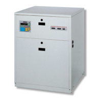
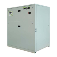
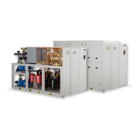
Description of NBW series units for civil and industrial applications.
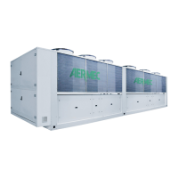
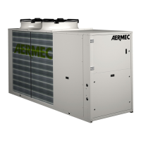
Overview of available NBW unit sizes, refrigerants, and version codes.
List and diagram of the primary components of the NBW unit.
Description of hermetic compressors used in NBW units.
Details on plate-type condensers and evaporators used.
Description of thermostatic valve, pressure switches, and filters.
Description of channel frame, liquid line filter, and spy glass.
Overview of functions managed by the microprocessor control card.
Details on microprocessor control of compressor activation and start-ups.
Management of water pump operation for utilities and external circuits.
Explanation of thermostat intervention steps for cooling and heating.
Details on autostart functions and pre-alarm/alarm handling.
List of safety interlocks, switches, and remote control panel.
Description of optional accessories like programmers and remote panels.
Descriptions of Pressure Valve (VP), By-pass Valve (VPH), and Vibration Dampers (VT).
Table showing accessory compatibility with different NBW models.
Cooling/heating capacity, power absorption, flow rates, and pressure drops.
Details on unit size, hydraulic/gas connections, and weight.
Cooling/heating capacity, power absorption, flow rates, and pressure drops.
Details on unit size, hydraulic/gas connections, and weight.
Guidelines on incorrect usage and potential hazards.
Explanation of various safety symbols used in the manual.
How to select the appropriate unit based on performance requirements.
Step-by-step example of selecting an NBW unit for a specific application.
Diagram showing operational limits based on water temperatures and glycol mix.
Definitions of key parameters like Tc, Twc, Twe, Atc, and Ate.
Chart showing pressure drops for evaporators across different flow rates.
Chart showing pressure drops for NBW condensers across different flow rates.
Chart showing pressure drops for NBW H condensers.
Table for applying correction factors to pressure drops based on water temperature.
Chart showing pressure drops for water filters at various flow rates.
Table showing correction factors for evaporator/condenser Delta T.
Table showing correction factors based on heat exchanger fouling.
Table detailing sound pressure and power levels for different models.
Table showing adjustable control parameters and their ranges.
Table listing settings for safety devices like pressure switches.
Correction factors for glycol/water solutions affecting capacity and flow.
Data on refrigerant line lengths, diameters, and gas per meter.
Instructions for safe lifting, transport, and unit placement.
Guidance on connecting hydraulic systems and recommended accessories.
Schematic of the hydraulic circuit for NBW cooling-only units.
Schematic of the hydraulic circuit for NBW H in cooling mode.
Schematic of the hydraulic circuit for NBW H in heating mode.
Information regarding factory wiring and electrical standards compliance.
Checks required before initial unit startup, including system charge and voltage.
Guidance on starting the unit and consulting the user manual for details.
Procedures for charging/draining systems to prevent freezing damage.
Overall dimensions and connection port locations for NBW 142-2027 models.
Dimensions for the anti-vibration pad mounting holes.
Overall dimensions and connection port locations for NBW 302-6027 models.
Overall dimensions and connection port locations for NBW 302E-6027E models.
Dimensions of the PR remote control panel.
Data (A, B dimensions) for VT antivibration pads.
Key to symbols used in the refrigerant circuit diagrams.
Schematic layout of refrigerant circuits for NBW 142-2027 H models.
Schematic layout of refrigerant circuits for NBW 302-6027 H models.
Schematic layout of refrigerant circuits for NBW 302E-6027E models.
Key to symbols and abbreviations used in electrical wiring diagrams.
Table of electrical data for different NBW models (cable sizes).
Diagram showing DIP-switch configurations for NBW units.
Schematic of the electronic board and its terminal connections.
Diagram showing DIP-switch configurations for NBW-H units.
Schematic of the NBW-H electronic board and its terminal connections.
Schematic for auxiliary connections of NBW 142 and 302 series units.
Schematic for auxiliary connections of NBW 202 and 2027 series units.
Schematic for auxiliary connections of NBW 402 and 602 series units.
Schematics for safety connections in NBW 142-4027 series units.
Load connection diagrams for NBW 142-3027 models.
Load connection diagrams for NBW 142H-3027H models.
Load connection diagrams for NBW 402-6027 models.
Load connection diagrams for NBW 402H-6027H models.
Diagram for NBW-E single fan circuit wiring.
Diagram for NBW-E dual fan circuit wiring.
Diagram for NBW-E 202-2027 E single fan circuit wiring.
Diagram for NBW-E 202-2027 E dual fan circuit wiring.
Diagram for NBW-E 302-3027 E single fan circuit wiring.
Diagram for NBW-E 302-3027 E dual fan circuit wiring.
Diagram for NBW-E 402-6027 E single fan circuit wiring.
Diagram for NBW-E 402-6027 E dual fan circuit wiring.