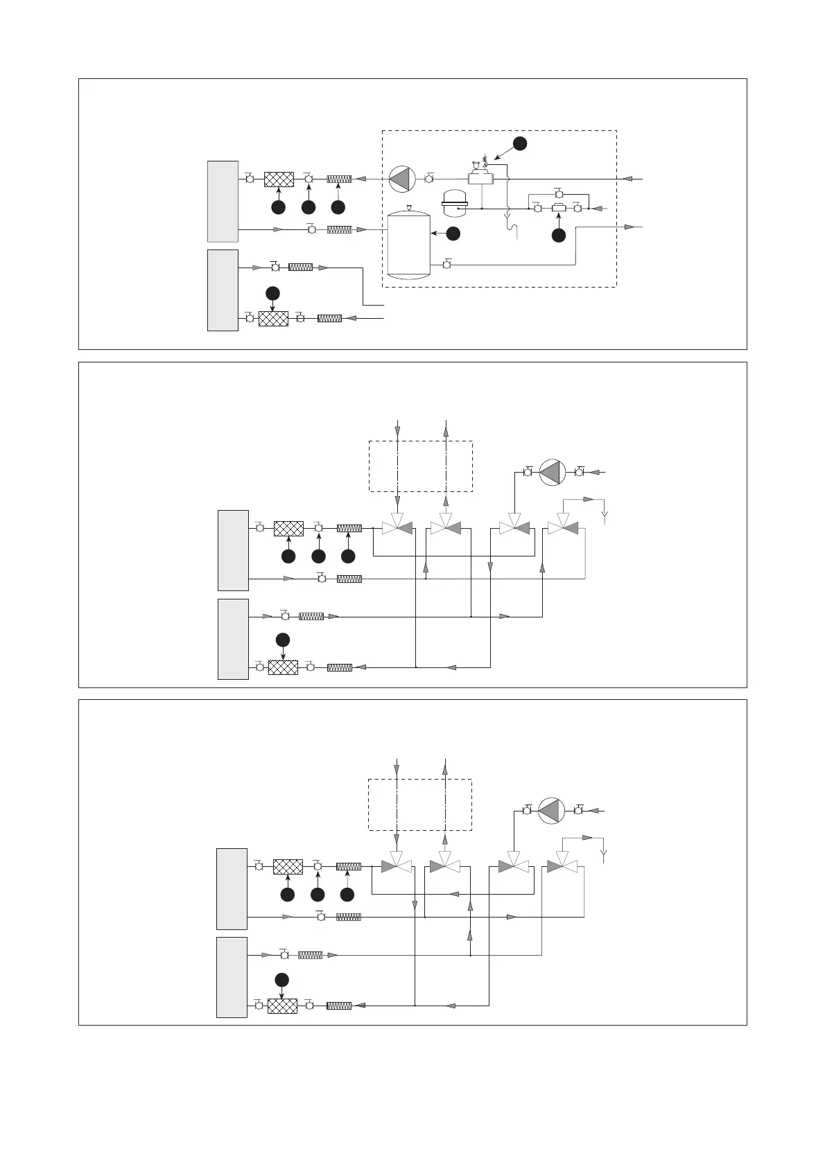
NBW H in riscaldamento • NBW H in heating mode
Negli schemi delle versioni a pompa di calore il rettangolo tratteggiato rappresenta i componenti consigliati nel rettangolo
tratteggiato nella versione solo freddo.
In the heat pump version diagrams, the broken-line rectangle represents the recommended parts in the broken-line rectangle
in the cooling only version.
Circuito esterno
To the external circuit
Circuito utenze
To the installation circuit
Circuito esterno
To the external circuit
Circuito utenze • To the installation circuit
Circuito esterno
To the external circuit
Circuito utenze • To the installation circuit
 Loading...