42
ELECTRONIC ADJUSTMENT
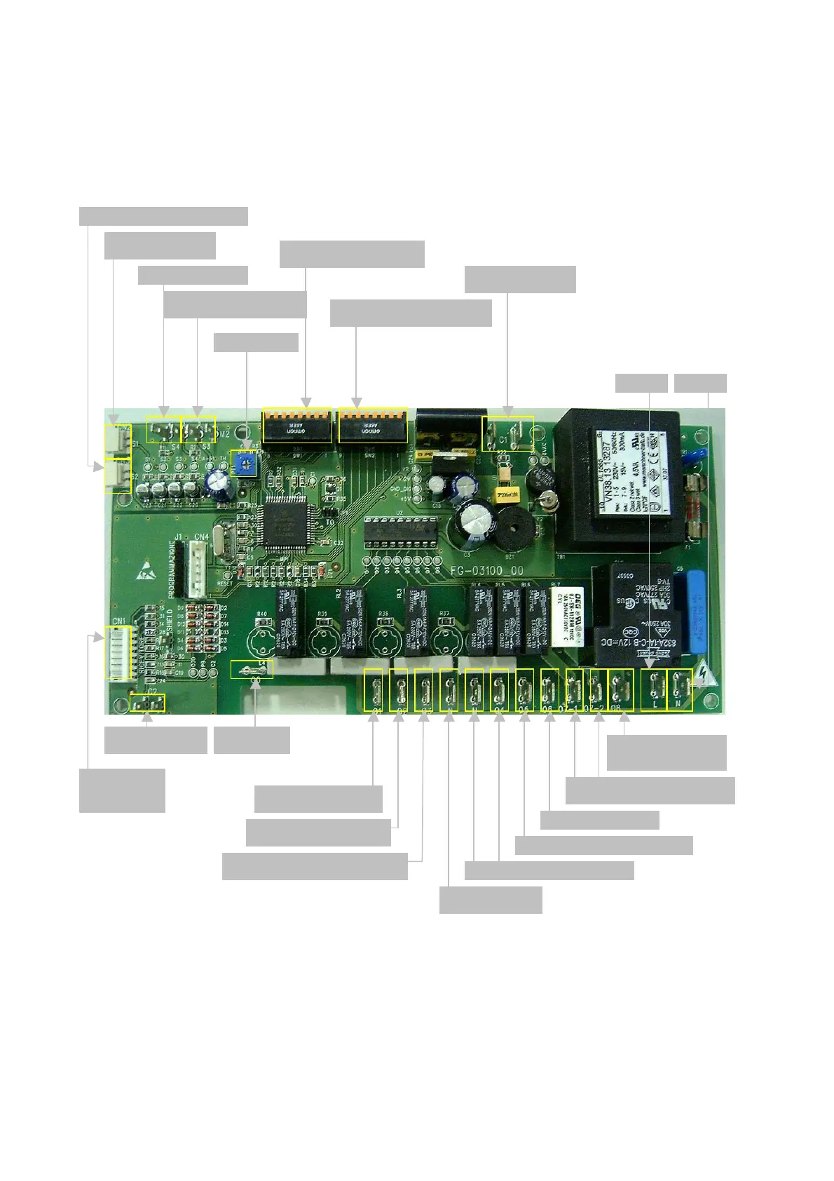
The card for commanding the cassette is shown below, with an indication of the outputs
S2: sonda batteria (acqua o gas)
Neutro
S1: sonda ambiente
S4: NTC resistenza
S3: seconda NTC o sonda
acqua
PT1: Trimmer
SW1: dip switc h 1, da 8 di p
SW2: dip switch 1, da 8 dip
C1: contatto esterno
Linea
O7_1 O7_2: resistenza/valvola
acqua ECL
O6: Y1 FCL , VI ECL
O5: MA motore aletta continuo
N ,O4: Y 2 F C L, MV EC L
neutro ventilatore
O3: V3 velocità massima ventilatore
O2: V2 velocità intermerdia
O1: V1 velocita minima
O0: Non
collegato
C2: AL1 Allarme
CN1:
Ricevitore/PF
O8: RE FCL,
compressore ECL