46
English
This contact in the terminal box allows to
have a signal (230V ~, max 1A) with which
to control the system pump. The table
shows the voltage at this contact depend-
ing on the machine version, the unit sta-
tus and the status of the internal valve.
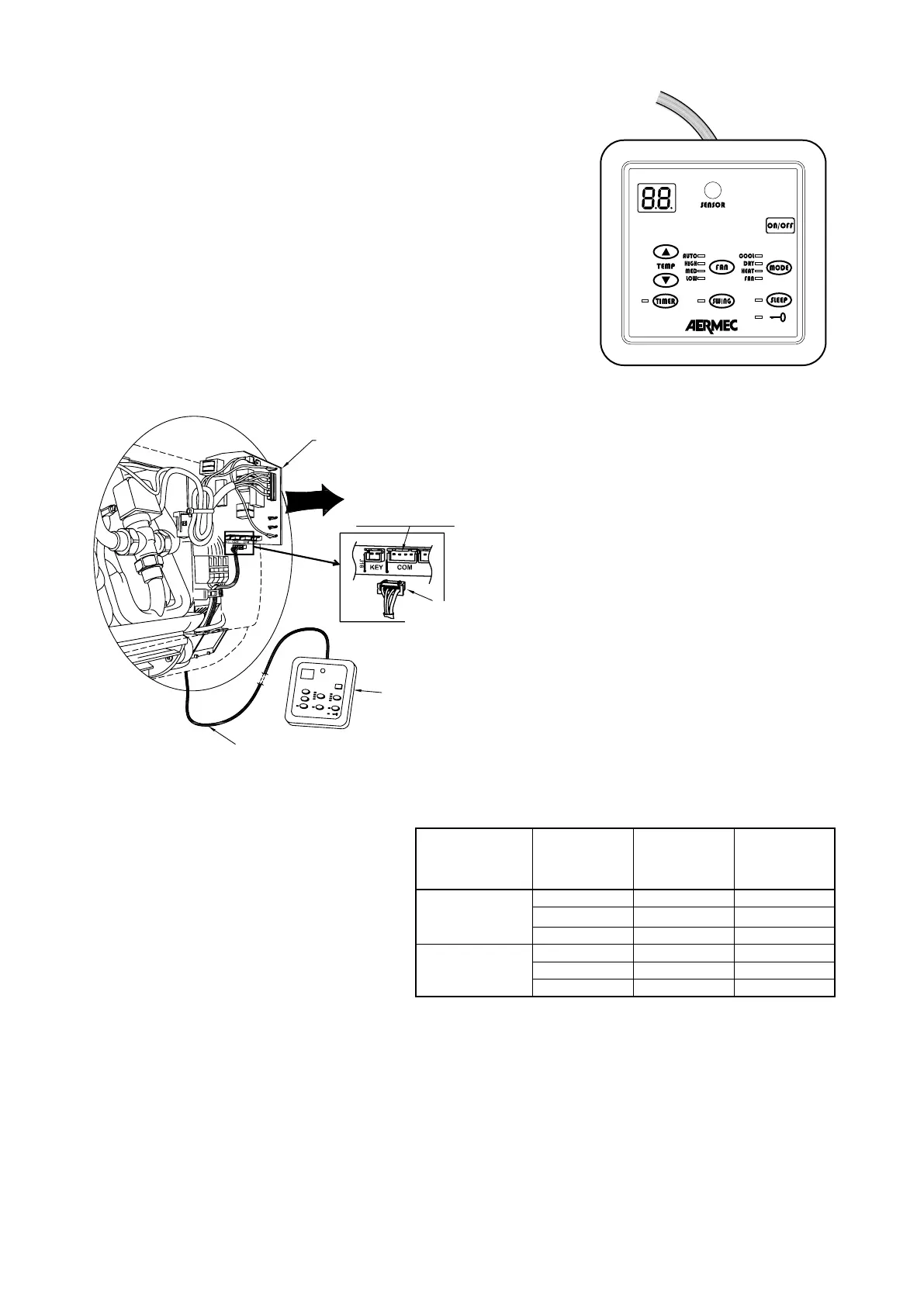
PFW2
Microprocessor
controller
Remove the circuit board
Female socket
Male connector of
wired control panel
Wired control panel
Wired control panel
cable
INSTALLATION OF PFW2 WIRED CON
ing of the fan coil unit. Alternative to the
A PFW2 wired control panel can only con-
trol one fan coil unit.
The panel can be fixed directly to the wall
with two screws or a rectangular electri-
cal box. The panel cable is 7.5 metres
long and is fitted with connector (B) for
connection to the fan coil circuit board as
shown in the wiring diagrams.
To install the wired control panel it is nec-
essary:
- to disconnect the connector (A) of the
infrared receiver from the circuit board
inside the fan coil unit.
- connect connector (B) of the wired con-
trol panel to the circuit board connector
now vacant.
The PFW2 makes it possible to set the
operating parameters of the unit and
these parameters are shown on a liq-
uid crystal display, making programming
operations easier.
light.
FCW version VALVE status/
3V
OFF OFF 0 V
ON ON 230V~
ON OFF 230V~
2V, VL
OFF OFF 0 V
ON ON 230V~
ON OFF 0 V