30
FWR 1406 - 5388000_02
TL3 CONTROLLER
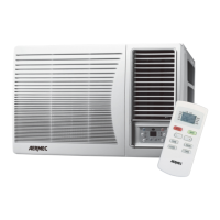
The control device consists of a remote controller and an infra red
receiver.
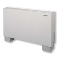
The IR receiver can be installed:
- On-board of the unit, the IR receiver is placed under the grid,
invisible from the outside.
- Encased in the wall and connected to the unit with the dedi-
cated cable (8 meters).
The receiver is supplied with an 8 metre long cable for connec-
tion to within the unit, an 3 module Type 503 rectangular box (of
which only 1 is occupied by the receiver, the others are available
for other uses), and a white coloured cover plate.
For the installation of the second TL3 connect in parallel with the
8 metre long cable included, the second receiver to the first.
Avoid mounting the receiver in positions directly exposed to
sunlight.
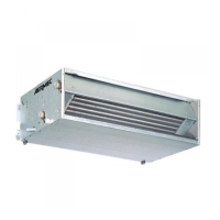
2 BLU-BLUE-BLEU-BLAU
6 NERO-BLACK-NOIR-SCHWARZ
5 BIANCO-WHITE-BLANC-WEISS
4 GIALLO-YELLOW-
3 MARRONE-BROWN-MARRON-BRAUN
1 ROSSO-RED-ROUGE-ROT
6
1
2
3
4
5
1 = Red
2 = Blue
3 = Brown
4 = Yellow
5 = White
6 = Black
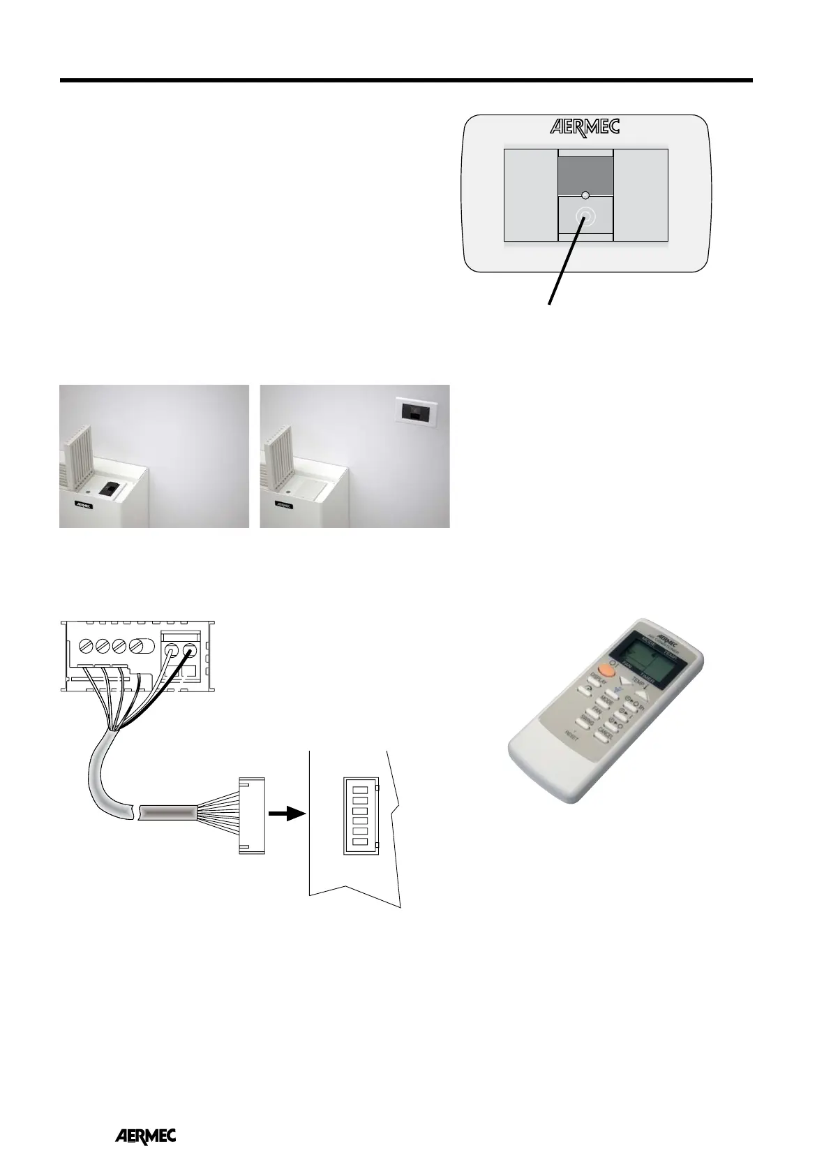
ELECTRICAL CONNECTIONS TL3
“AUX” BUTTON (AUXILIARY CONTROLLER)
This is used when the remote controller is out of service.
Allows starting only in AUTO operating mode and switch-
ing of the air conditioner.
In AUTO mode the microprocessor determines at start
up, based on the ambient temperature, the required
operating mode, and determines the temperature to be
maintained and sets the fan speed.
FW_R
ACCESSORIES DATA
TL3 receiver mounted on board TL3 receiver mounted on the wall