Do you have a question about the AERMEC NLC 0280 and is the answer not in the manual?
Overview of hazards and warning symbols used in the manual.
Key safety advice for handling and operating the unit.
Guidelines for proper unit installation and compliance.
Fundamental safety regulations for personnel.
Safety measures for the unit's water circuit.
Safety measures for the unit's electrical connections.
Safety measures for the refrigerant cooling circuit.
General safety advice and preventative measures.
Identification of safety labels and their meanings.
Selection advice for units installed in marine or coastal areas.
Selection advice for units in industrial settings with emissions.
Selection advice for combined corrosive environments.
Selection advice for units in densely populated areas.
Selection advice for units in rural areas with potential pollution.
Factors influencing heat exchanger selection beyond environment type.
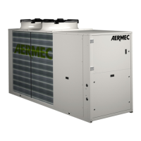
Description of reversible heat pumps and general safety.
Key requirements for unit installation and system design.
Charts showing unit operation limits based on air temperature.
Charts showing unit operation limits at high static pressure.
Charts showing unit operation limits based on air temperature.
Charts showing unit operation limits based on air temperature.
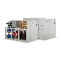
Schematic diagram of the refrigerant circuit for specific models.
Schematic diagram of the refrigerant circuit for specific models.
Steps for checking unit upon arrival and identifying it.
Guidelines for safely removing packaging and handling the unit.
Procedures for lifting the unit using hoists or cranes.
Procedures for moving the unit using a forklift.
Guidelines for storing the unit before installation.
Criteria for selecting an appropriate installation location.
Advice on properly positioning the unit for operation and maintenance.
Minimum clearances needed around the unit for safety and maintenance.
How to set the fan speed for optimal air flow and pressure.
Diagrams showing vibration damper placement for specific models.
Diagrams showing vibration damper placement for specific models.
Diagrams showing vibration damper placement for specific models.
Diagrams showing vibration damper placement for specific models.
Weight distribution and center of gravity when the unit is empty.
Weight distribution and center of gravity during operation.
Compatibility of VT antivibration supports with unit configurations.
Compatibility of AVX antivibration supports with unit configurations.
Empty and functioning weights for different hydronic kit options.
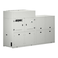
Physical dimensions for unit models 0280 through 0350.
Physical dimensions for unit models 0550 through 0675.
Physical dimensions for unit model 0750.
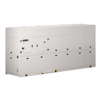
Physical dimensions for unit models 0800 through 1250.
Connection diagrams for unit models 0280-0350.
Connection diagrams for unit models 0550-0675.
Connection diagrams for unit models 0750-1250.
Advice on connecting hydraulic circuits and pipe support.
Recommended water quality and treatment for heat exchangers.
Procedures for draining the system to prevent freezing.
Methods for protecting the system from freezing, including glycol use.
Required minimum water volume for stable unit operation.
Maximum water volume based on unit configuration and expansion vessel.
How to adjust expansion vessel pre-charge pressure based on installation height.
Schematic for NLC 0280-1250 (00) main hydraulic circuit.
Schematic for NLC 0280-1250 (P1-P2-P3-P4) main hydraulic circuit.
Schematic for NLC 0280-1250 (01-02-03-04) main hydraulic circuit.
Recommended water quality for hydraulic circuits.
Electrical specifications like peak current and amperage for different power supplies.
Electrical data specific to single hydronic kit configurations.
Steps for safely connecting the unit to the electrical mains.
Steps to perform before powering on the unit.
Checks to conduct with no voltage applied to the unit.
Safety precautions when performing checks with the unit running.
Verifying proper operation of hydraulic circuit components.
Final steps to commission the unit after all checks are complete.
General safety rules and preventative steps for maintenance.
Safety measures related to chemical hazards, fire, and environmental impact.
Safety measures for risks associated with high/low pressure and temperature.
Safety measures to prevent electrical hazards during maintenance.
Procedures for regular and non-routine maintenance tasks.
Guidelines for safely removing and disposing of unit components.
List of general maintenance tasks and their recommended frequency.
Maintenance tasks for the cooling circuit, including compressor and fan controls.
Maintenance tasks for the hydraulic system, including pump and water filter.
Overview of fields and options for configuring the unit's features.
Compatibility of communication and control accessories.
Compatibility of antivibration supports with unit models.
Compatibility of duct flanges with unit models.
Factory-installed accessories and their compatibility.
Compatibility of water filters with unit models.
Compatibility of peak current reduction devices.
Compatibility of power factor correction devices.
Compatibility of anti-condensate electric heaters.