D
Diane NormanAug 15, 2025
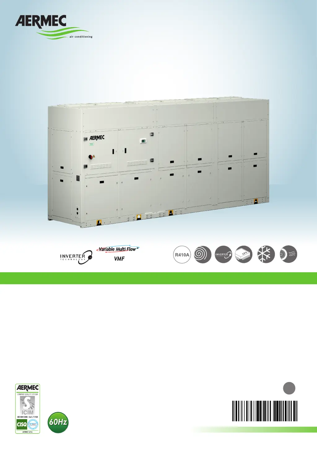
Why does my AERMEC Chiller compressor stop due to protection intervention?
- TTammy TaylorAug 15, 2025
The compressor may stop due to several reasons: excessive flow pressure, low intake pressure, low power supply voltage, badly tightened electrical connections, or operation outside operating limits. Check the operating limits using the graphics. A malfunctioning pressure switch can also cause this, so replace the component if needed. Additionally, check the power supply voltage and calibrations, as well as the electrical isolation of the windings, if the circuit breaker protection has been triggered. Finally, check the water flow rate if the flow switch has intervened.