20 - EN
EN
NLC_A cod: 1606.4037360_00
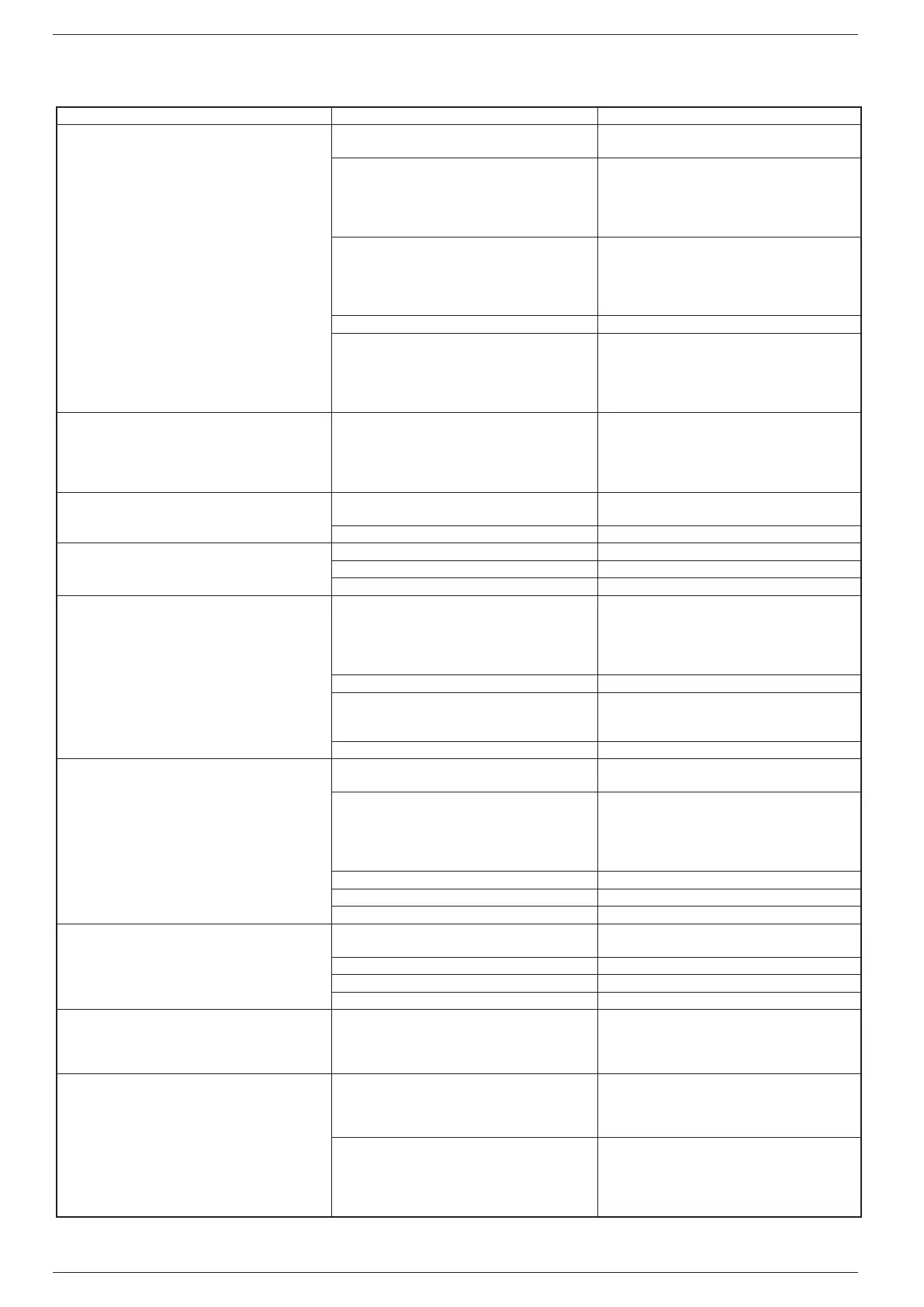
IRREGULARITY CAUSE SOLUTION
The unit does not
start
• No electrical voltage
• Check
for voltage
• Check the safety systems upstream of the appliance
• Master switch on OFF
• Remote switch on OFF (if present)
• Control panel on OFF
• Main switch on OFF
• Compressor thermomagnetic switch on OFF
• Set
to ON
• The flow switch is not connected on the termi-
nal board therefore the circuit is open
• Install and wire the flow switch
• NB. DO NOT bridge the contacts on the terminal
board (otherwise the unit will not stop in the event
of insufficient water and the exchanger would be to
throw away!)
• Power supply voltage too low • Check power supply line
• Coil of the compressor remote control switch
is broken
• Electronic circuit board faulty
• Peak condenser faulty
• Compressor faulty
• Replace
the component
Poor yield
• No refrigerant
• Dirty coils
• Water filter clogged
• Appliance dimensioning
• Operating outside the operating limits
• Check the load and any leaks
• Clean the coils
• Clean the filter
• Check performance
• Check the operating limits using the graphics
Compressor
noisy
• Liquid return to the compressor
• Inadequate fixing
• Check
• Inverted phase • Invert a phase
Noises
and vibrations
• Contact between metallic bodies • Check
• Weak support • Strengthen
• Loose screws • Tighten the screws
The
compressor stops due to the intervention of the
protections
• Excessive flow pressure
• Low intake pressure
• Low power supply voltage
• Electrical connections tightened badly
• Operation outside operating limits
• Check the operating limits using the graphics
• Pressure switch malfunctioning • Replace the component
• Circuit breaker protection intervention
• Check the power supply voltage and calibra
-
tions
• Check the electrical isolation of the winding
s
• Flow switch intervention • Check water flow rate
Compressor
high discharge pressure
• High external air temperature
• High utility inlet water temperature
• Check the operating limits using the graphics
• Insufficient air flow
• Insufficient water flow
• Control:
1. operation of the fans
2. Cleanliness of the coil
3. Operation of the pump (speed)
4. Cleanliness of the filter
• Anomalous operation adjusting the fans • Check or replace if broken
• Air in the hydraulic system • Vent the circuit
• Too much refrigerant gas charged • Restore the correct charge
Low
discharge pressure
• Low outside air temperature
• Low water inlet temperature
• Check the operating limits using the graphics,
as above
• Moisture in the refrigerant circuit • Empty and restore the gas charge
• Air in the hydraulic system • Bleed the circuit
• Insufficient gas load • Restore the correct load
High
intake pressure
• High external air temperature
• High utility inlet water temperature
• Thermostatic expansion valve too open or
damaged
• Check the operating limits using the graphics
• Adjust or replace if damaged
Low
intake pressure
• Utilities low inlet water temperature
• Low outside air temperature
• Thermostatic expansion valve damaged or
blocked
• Check the operating limits using the graphics
• Adjust or replace if damaged
• Insufficient water flow
• Insufficient air flow
• Control:
1. operation of the fans
2. Cleanliness of the coil
3. Pump operation (speed)
4. Filter cleanliness
18. TROUBLESHOOTING